Fast Ethernet Switching System User’s Guide
CPU Module
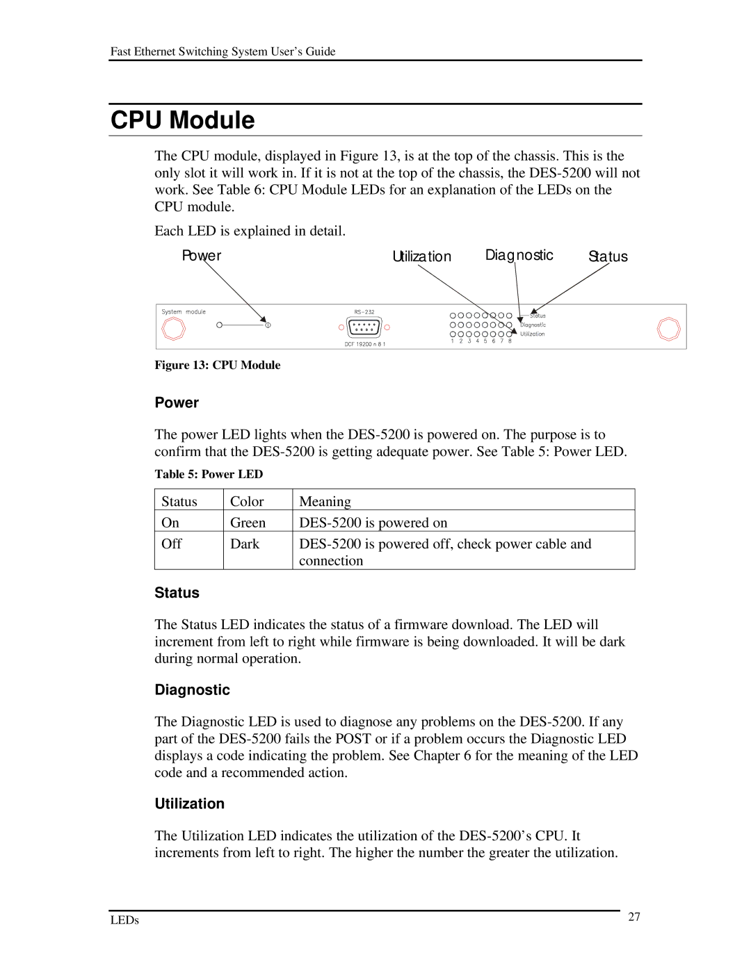
The CPU module, displayed in Figure 13, is at the top of the chassis. This is the only slot it will work in. If it is not at the top of the chassis, the
Each LED is explained in detail.
Power |
|
|
|
|
|
|
| Utilization |
| Diagnostic | Status | ||||||||||
|
|
|
|
|
|
|
|
|
|
|
|
|
|
|
|
|
|
|
|
|
|
|
|
|
|
|
|
|
|
|
|
|
|
|
|
|
|
|
|
|
|
|
|
|
|
|
|
|
|
|
|
|
|
|
|
|
|
|
|
|
|
|
|
|
|
|
|
|
|
|
|
|
|
|
|
|
|
|
|
|
|
|
|
|
|
|
|
|
|
|
|
|
|
|
|
|
|
|
|
|
|
|
|
|
|
|
|
|
|
|
|
|
|
|
|
|
|
|
|
|
|
|
|
|
|
|
|
|
|
|
|
|
|
|
|
|
|
|
|
|
|
|
|
|
|
|
|
|
|
|
|
|
|
|
|
|
|
|
|
|
|
|
|
|
|
|
|
|
|
|
|
|
|
|
|
|
|
|
|
|
|
|
|
|
|
|
|
|
|
|
|
|
|
|
|
|
|
|
|
|
|
|
|
|
|
|
|
|
|
|
|
|
|
|
|
|
|
|
|
Figure 13: CPU Module
Power
The power LED lights when the
Table 5: Power LED
Status | Color | Meaning |
On | Green | |
Off | Dark | |
|
| connection |
Status |
|
|
The Status LED indicates the status of a firmware download. The LED will increment from left to right while firmware is being downloaded. It will be dark during normal operation.
Diagnostic
The Diagnostic LED is used to diagnose any problems on the
Utilization
The Utilization LED indicates the utilization of the
LEDs | 27 |
