| Telephone Interface Description |
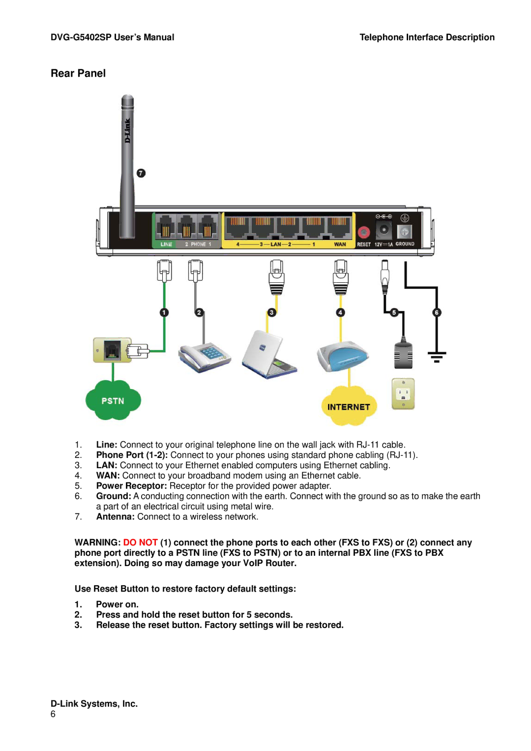
Rear Panel
1.Line: Connect to your original telephone line on the wall jack with
2.Phone Port
3.LAN: Connect to your Ethernet enabled computers using Ethernet cabling.
4.WAN: Connect to your broadband modem using an Ethernet cable.
5.Power Receptor: Receptor for the provided power adapter.
6.Ground: A conducting connection with the earth. Connect with the ground so as to make the earth a part of an electrical circuit using metal wire.
7.Antenna: Connect to a wireless network.
WARNING: DO NOT (1) connect the phone ports to each other (FXS to FXS) or (2) connect any phone port directly to a PSTN line (FXS to PSTN) or to an internal PBX line (FXS to PBX extension). Doing so may damage your VoIP Router.
Use Reset Button to restore factory default settings:
1.Power on.
2.Press and hold the reset button for 5 seconds.
3.Release the reset button. Factory settings will be restored.