DATALOGIC | DS4300 |
2.3.2 Junction Box Electrical Connections
The connection and wiring procedure for the junction box is described as follows:
1)Open the junction box by unscrewing the 4 cover screws.
2)Pass all System cables through the glands in the junction box housing.
3)To connect the power and input/output signals:
•Prepare the individual wires of the system cables by stripping the insulation back approximately 11 mm.
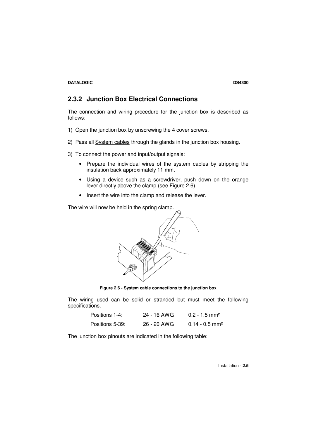
•Using a device such as a screwdriver, push down on the orange lever directly above the clamp (see Figure 2.6).
•Insert the wire into the clamp and release the lever.
The wire will now be held in the spring clamp.
Figure 2.6 - System cable connections to the junction box
The wiring used can be solid or stranded but must meet the following
specifications. |
|
|
Positions | 24 - 16 AWG | 0.2 - 1.5 mm² |
Positions | 26 - 20 AWG | 0.14 - 0.5 mm² |
The junction box pinouts are indicated in the following table:
Installation - 2.5