Cause:
Beeper:
Display:
Reset:
Cause:
Effect:
Beeper:
Display:
Reset:
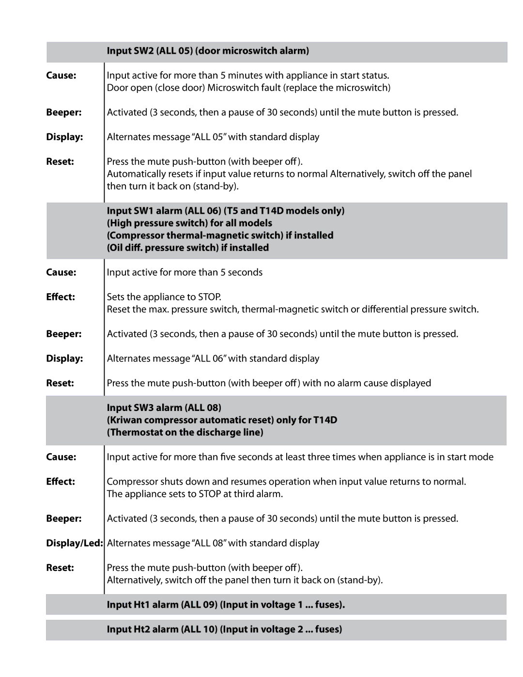
Input SW2 (ALL 05) (door microswitch alarm)
Input active for more than 5 minutes with appliance in start status. Door open (close door) Microswitch fault (replace the microswitch)
Activated (3 seconds, then a pause of 30 seconds) until the mute button is pressed.
Alternates message “ALL 05” with standard display
Press the mute
Automatically resets if input value returns to normal Alternatively, switch off the panel then turn it back on
Input SW1 alarm (ALL 06) (T5 and T14D models only) (High pressure switch) for all models (Compressor
Input active for more than 5 seconds
Sets the appliance to STOP.
Reset the max. pressure switch,
Activated (3 seconds, then a pause of 30 seconds) until the mute button is pressed.
Alternates message “ALL 06” with standard display
Press the mute
Input SW3 alarm (ALL 08)
(Kriwan compressor automatic reset) only for T14D (Thermostat on the discharge line)
Cause:
Effect:
Beeper:
Display/Led:
Reset:
Input active for more than five seconds at least three times when appliance is in start mode
Compressor shuts down and resumes operation when input value returns to normal. The appliance sets to STOP at third alarm.
Activated (3 seconds, then a pause of 30 seconds) until the mute button is pressed.
Alternates message “ALL 08” with standard display
Press the mute
Alternatively, switch off the panel then turn it back on
Input Ht1 alarm (ALL 09) (Input in voltage 1 ... fuses).
Input Ht2 alarm (ALL 10) (Input in voltage 2 ... fuses)