T5, T14D, T20C, T24C, T40
Blast Chiller/Shock Freezers
Service, Installation and Care Manual
Please read this manual completely before attempting to install or operate this equipment! Notify carrier of damage! Inspect all components immediately. See page 2.
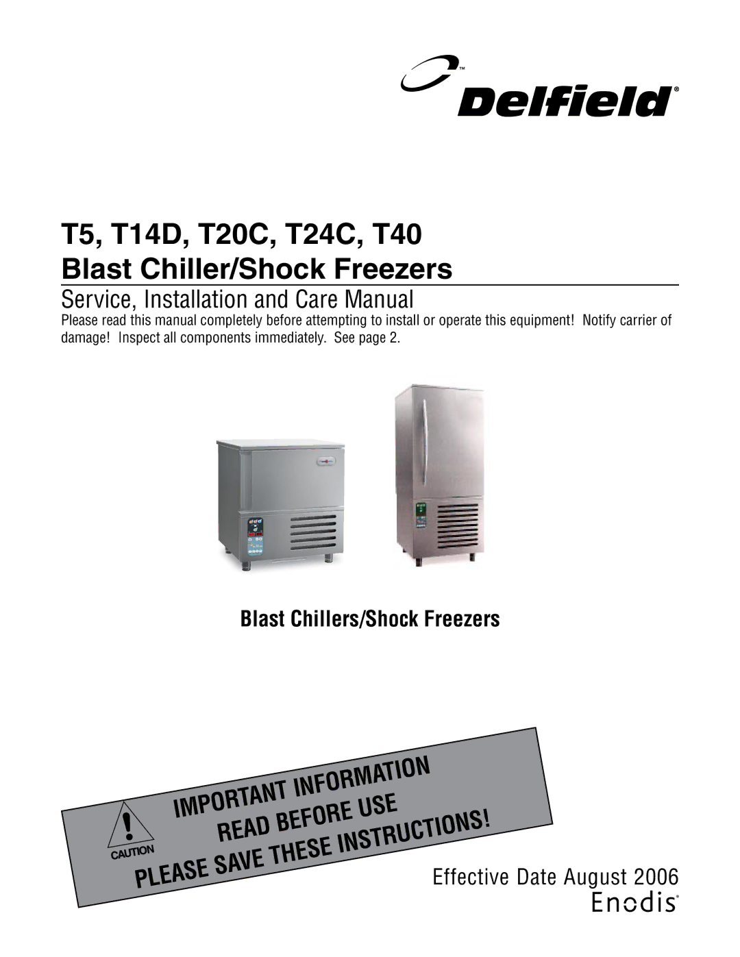
Blast Chillers/Shock Freezers
IMPORTANT | INFORMATION | |||||
|
| USE | ||||
| READ | BEFORE |
| |||
|
|
| INSTRUCTIONS! | |||
| SAVE | THESE | ||||
PLEASE |
| Effective Date August 2006 | ||||
|
|
|
| |||
|
|
|
|
| ||