Figure B-6. Pin Numbers for the Keyboard Connector
Table B-6. Pin Assignments for the Keyboard Connector
Pin | Signal | I/O | Definition |
1 | KBDATA | I/O | Keyboard data |
2 | NC | N/A | No connection |
3 | GND | N/A | Signal ground |
4 | FVcc | N/A | Fused supply voltage |
5 | KBCLK | I/O | Keyboard clock |
6 | NC | N/A | No connection |
Shell | N/A | N/A | Chassis ground |
Mouse Connector
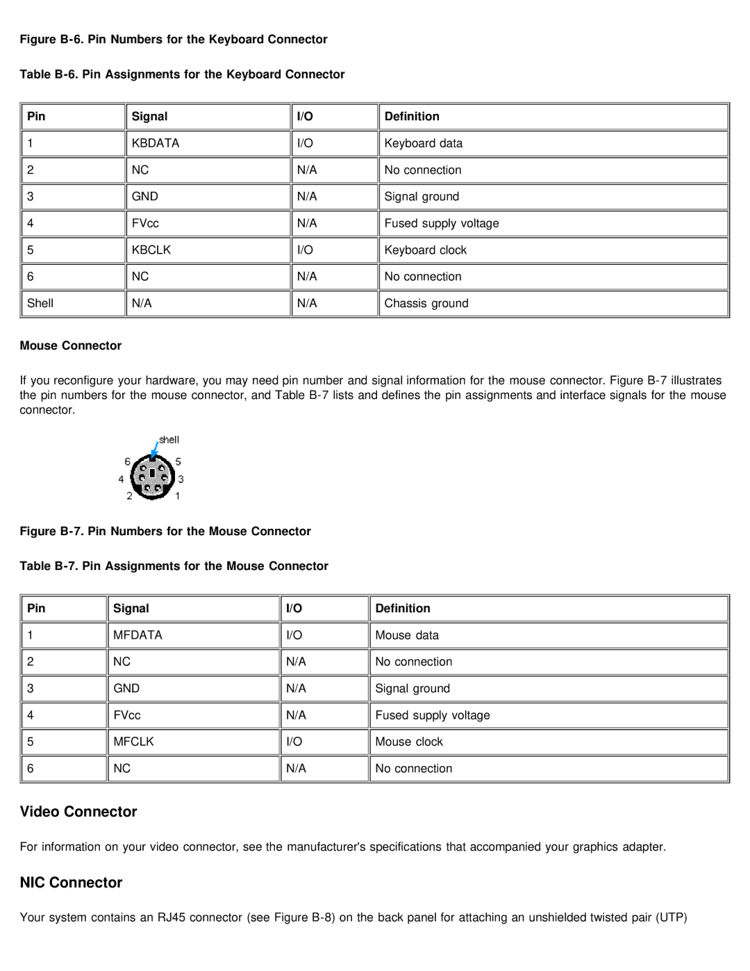
If you reconfigure your hardware, you may need pin number and signal information for the mouse connector. Figure
Figure B-7. Pin Numbers for the Mouse Connector
Table B-7. Pin Assignments for the Mouse Connector
Pin | Signal | I/O | Definition |
1 | MFDATA | I/O | Mouse data |
2 | NC | N/A | No connection |
3 | GND | N/A | Signal ground |
4 | FVcc | N/A | Fused supply voltage |
5 | MFCLK | I/O | Mouse clock |
6 | NC | N/A | No connection |
Video Connector
For information on your video connector, see the manufacturer's specifications that accompanied your graphics adapter.
NIC Connector
Your system contains an RJ45 connector (see Figure
