Dell™ Latitude™ E6400 XFR Service Manual
|
|
|
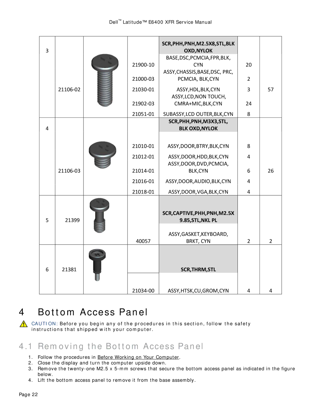
| SCR,PHH,PNH,M2.5X8,STL,BLK |
|
|
3 |
|
|
| OXD,NYLOK |
|
|
|
|
|
| BASE,DSC,PCMCIA,FPR,BLK, |
|
|
|
|
| 21900‐10 | CYN | 20 |
|
|
|
|
| ASSY,CHASSIS,BASE,DSC, PRC, |
|
|
|
|
| 21000‐03 | PCMCIA, BLK,CYN | 2 |
|
| 21106‐02 |
| 21030‐01 | ASSY,HDL,BLK,CYN | 3 | 57 |
|
|
|
| ASSY,LCD,NON TOUCH, |
|
|
|
|
| 21902‐03 | CMRA+MIC,BLK,CYN | 24 |
|
|
|
| 21051‐01 | SUBASSY,LCD OUTER,BLK,CYN | 8 |
|
|
|
|
| SCR,PHH,PNH,M3X3,STL, |
|
|
4 |
|
|
| BLK OXD,NYLOK |
|
|
|
|
| 21010‐01 | ASSY,DOOR,BTRY,BLK,CYN | 8 |
|
|
|
| 21012‐01 | ASSY,DOOR,HDD,BLK,CYN | 4 |
|
|
|
|
| ASSY,DOOR,DVD,PCMCIA, |
|
|
| 21106‐03 |
| 21014‐01 | BLK,CYN | 6 | 26 |
|
|
| 21016‐01 | ASSY,DOOR,AUDIO,BLK,CYN | 4 |
|
|
|
| 21018‐01 | ASSY,DOOR,VGA,BLK,CYN | 4 |
|
|
|
|
| SCR,CAPTIVE,PHH,PNH,M2.5X |
|
|
5 | 21399 |
|
| 9.85,STL,NKL PL |
|
|
|
|
|
| ASSY,GASKET,KEYBOARD, |
|
|
|
|
| 40057 | BRKT, CYN | 2 | 2 |
6 | 21381 |
|
| SCR,THRM,STL |
|
|
|
|
| 21034‐00 | ASSY,HTSK,CU,GROM,CYN | 4 | 4 |
4 Bottom Access Panel
CAUTION: Before you begin any of the procedures in this section, follow the safety instructions that shipped with your computer.
4.1 Removing the Bottom Access Panel
1.Follow the procedures in Before Working on Your Computer.
2.Close the display and turn the computer upside down.
3.Remove the
4.Lift the bottom access panel to remove it from the base assembly.
Page 22