W . d e l l . c o m s u p p o r t . d e l l . c o m
September T8144
Contents
Solving Problems
Mail, Modem, and Internet Problems
Before Working Inside Your Computer
Addressing Memory With 4-GB Configurations
Resolving Software and Hardware Incompatibilities
Connecting and Disconnecting Drive Cables
103
105
109
111
Contents
Finding Information
What Are You Looking For? Find It Here Warranty information
Finding Information
Use the Service Tag to
When you use
Microsoft Windows License Label
Identify your computer
Printer Cable
Setting Up a Printer
Setting Up and Using Your Computer
USB connector on computer USB printer cable
Connecting to the Internet
Connecting a Printer
Setting Up Your Internet Connection
Next window, click the appropriate option
Playing CDs and DVDs
DVD player includes the following basic buttons
Adjusting the Volume
Adjusting the Picture
How to Copy a CD or DVD
Copying CDs and DVDs
Media Type Read Write Rewritable
Using Blank CDs and DVDs
Helpful Tips
Using a Media Card Reader Optional
Connecting Two Monitors
XD-Picture Card
II CF I/II
MicroDrive Card
Optional DVI adapter
Connecting Two Monitors With VGA Connectors
Follow the procedures in Before You Begin on
Setting Up a Home and Office Network
Connecting a TV
Changing the Display Settings
Connecting to a Network Adapter
On the welcome screen, click Next
Power Management
Network Setup Wizard
Power Options Properties
Standby Mode
Hibernate Mode
Power Schemes Tab
Hyper-Threading
Setting Up and Using Your Computer
Troubleshooting Tips
Battery Problems
Drive Problems
Solving Problems
CD and DVD drive problems
Problems writing to a CD/DVD-RW drive
Mail, Modem, and Internet Problems
Hard drive problems
Error Messages
These characters in filenames
Media Card Reader Problems
Keyboard Problems
Lockups and Software Problems
Computer does not start up
Computer stops responding
Solid blue screen appears
Program stops responding
Program crashes repeatedly
Memory Problems
Other software problems
Mouse Problems
Network Problems
Simultaneously press CtrlEsc to display the Start menu
Your computer Start the computer
Power Problems
Printer Problems
Scanner Problems
Sound and Speaker Problems
No sound from speakers
If the screen is blank
Video and Monitor Problems
No sound from headphones
If the screen is difficult to read
Solving Problems
Diagnostic Lights
If the problem persists or the computer has
Connector placement requirements exist
Computer
See
If there is an error message on your screen
Boot sequence is correct for the devices
Installed on your computer
Restart the computer
Dell Diagnostics
Dell Diagnostics Main Menu
If you cannot resolve the error condition, contact Dell see
Option Function
Tab Function
What Is a Driver?
Drivers
Reinstalling Drivers
Identifying Drivers
Resolving Software and Hardware Incompatibilities
Restoring Your Operating System
Using Microsoft Windows XP System Restore
Using Dell PC Restore by Symantec
Undoing the Last System Restore
Ensure that Turn off System Restore is unchecked
Click System
Troubleshooting Tools
Removing and Installing Parts
Before You Begin
Recommended Tools
Turning Off Your Computer
Before Working Inside Your Computer
Front View of the Computer
Computer. Instead, perform an operating system shutdown
Vents and any object near these vents
Insert the power cable
Back View of the Computer
Connector
Surround connector
Line-in connector
Line-out connector
Removing the Computer Cover
Inside View of Your Computer
System Board Components
Memory
DDR2 Memory Overview
Addressing Memory With 4-GB Configurations
Dimm connectors 3
Installing Memory
Removing Memory
Cards
PCI Cards
Release tab Card retention door
Bracket caught outside of slot
Alignment guide alignment bar
If you removed an add-in network connector
PCI Express Cards
Release tabs
X16 card X1 card Securing tab
Bracket caught
Release tabs
If you removed an add-in network connector
Sliding plate lever Drive panel
Drive Panel
Removing the Drive Panel
Removing the Drive-Panel Insert
Replacing the Drive-Panel Insert
Drive panel Insert tab Drive panel insert
Center drive Panel tab Drive panel insert
Replacing the Drive Panel
Connecting Drive Cables
Drives
IDE Drive Addressing
CD/DVD drives
Power cable Removing and Installing Parts
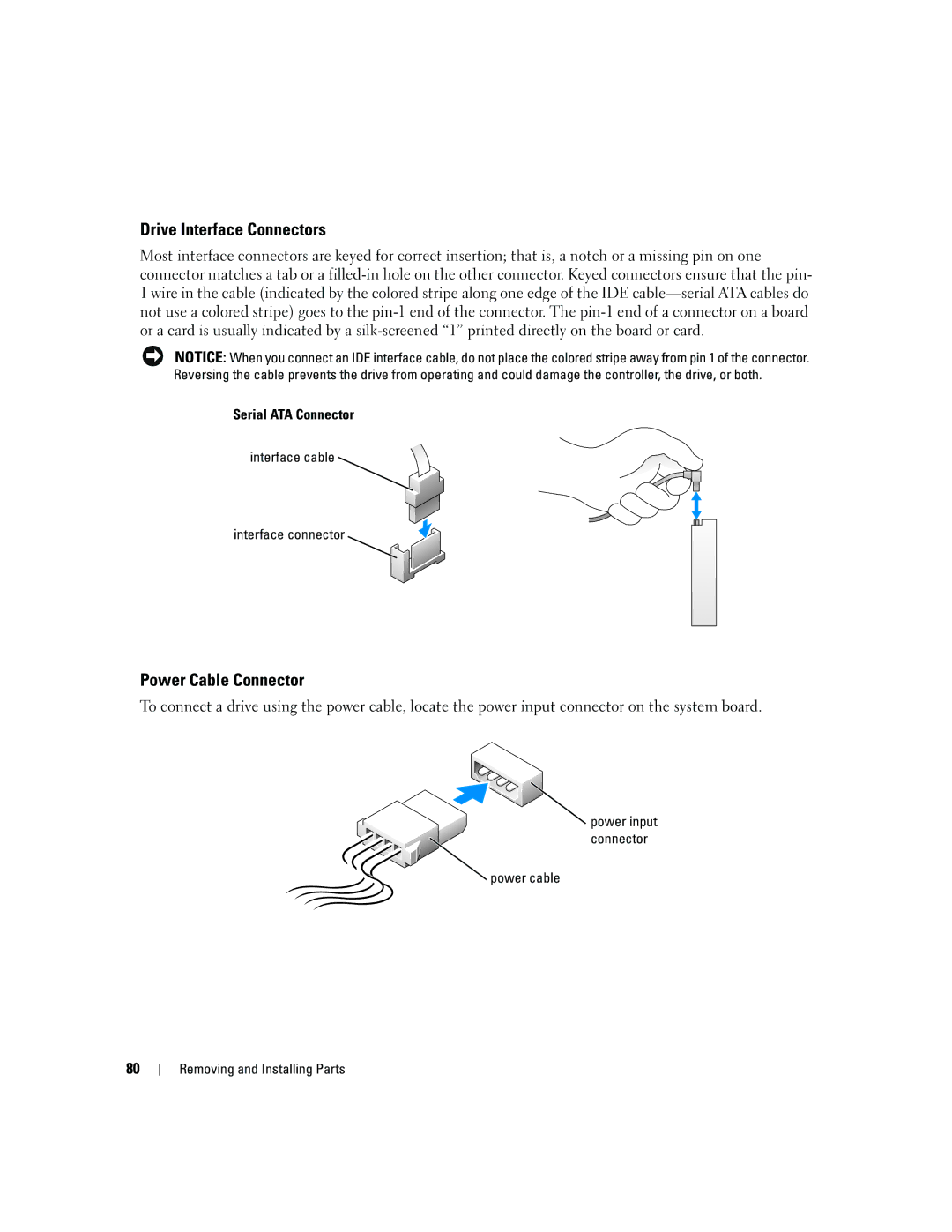
Drive Interface Connectors
Power Cable Connector
Connecting and Disconnecting Drive Cables
Hard Drive
Removing a Hard Drive
Power cable
Tabs Hard drive Removing and Installing Parts
Installing a Hard Drive
Drive Hard drive bracket
Adding a Second Hard Drive
Hard drive bay
Removing a Floppy Drive
Power cable Data cable
Floppy Drive
Page
Installing a Floppy Drive
Drive Screws
Power cable Data cable
Media Card Reader
Removing a Media Card Reader
Drive latch release Sliding plate Media Card Reader
Installing a Media Card Reader
Media Card Reader Screws
FlexBay USB cable Media Card Reader
Removing a CD/DVD Drive
Power cable Data cable Removing and Installing Parts
CD/DVD Drive
Page
Installing a CD/DVD Drive
Connect the power and data cables to the drive
Battery
Replacing the Battery
Replacing the Computer Cover
Computer cover Back of computer Bottom hinges
System clock Or 1066-MHz data rate Appendix
Specifications
Eight-way set associative, write-back Sram
100
Drive, and Media Card Reader
101
102
System Setup
Entering System Setup
Overview
103
Appendix
System Setup Options
105
On default
Determines the integrated Sata controller’s operating mode
106
Operating system that do not support Sata drives
107
108
Boot Sequence
109
Appendix
Clearing Forgotten Passwords
111
Clearing Cmos Settings
Cleaning Your Computer
Computer, Keyboard, and Monitor
Mouse
Floppy Drive
Definition of Dell-Installed Software and Peripherals
Dell Technical Support Policy U.S. Only
CDs and DVDs
114
FCC Notices U.S. Only
Definition of Third-Party Software and Peripherals
Class a
115
FCC Identification Information
Contacting Dell
Class B
117
118
119
120
121
122
123
124
125
126
127
128
Dell Precision Technical Support PowerApp, PowerEdge
Switchboard Sales
129
Countries Sales Penang, Malaysia Appendix
130
Trinidad/Tobago General Support Turks and Caicos Islands
PowerConnect, and PowerVault Transaction Sales
131
132
133
134
Index
Index 135
136 Index
Index 137
Device Driver Rollback, 48 Files and Settings Transfer
138 Index