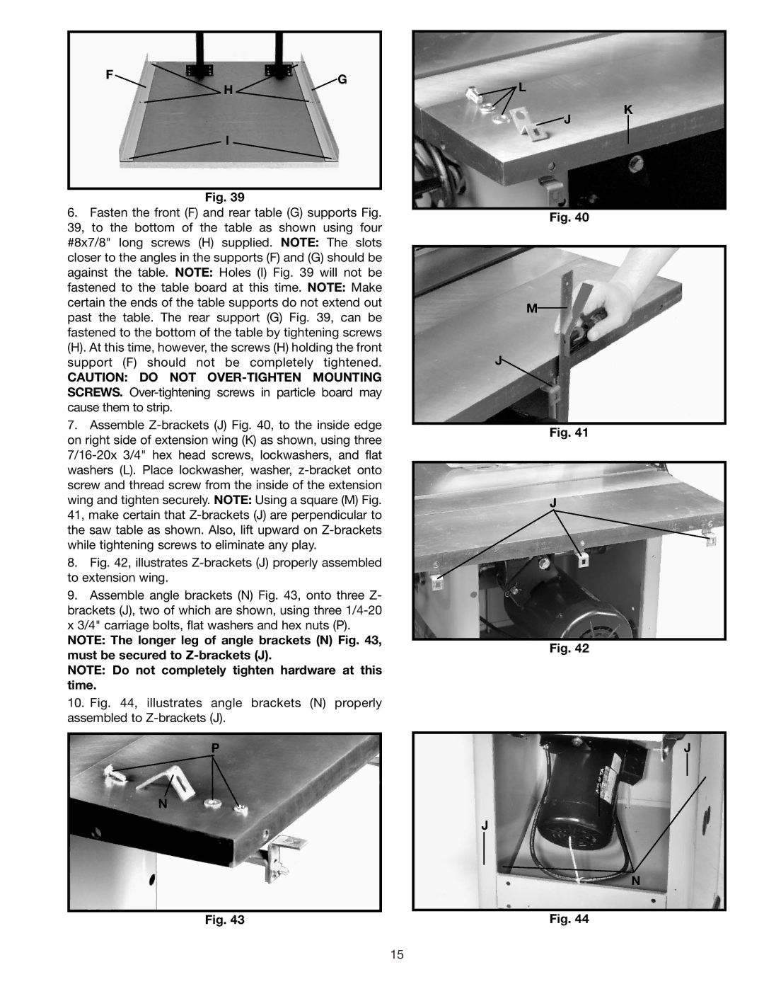
F | G |
| H |
| I |
Fig. 39
6.Fasten the front (F) and rear table (G) supports Fig. 39, to the bottom of the table as shown using four #8x7/8" long screws (H) supplied. NOTE: The slots closer to the angles in the supports (F) and (G) should be against the table. NOTE: Holes (I) Fig. 39 will not be fastened to the table board at this time. NOTE: Make certain the ends of the table supports do not extend out past the table. The rear support (G) Fig. 39, can be fastened to the bottom of the table by tightening screws
(H). At this time, however, the screws (H) holding the front support (F) should not be completely tightened.
CAUTION: DO NOT
7.Assemble
8.Fig. 42, illustrates Z-brackets (J) properly assembled to extension wing.
9.Assemble angle brackets (N) Fig. 43, onto three Z- brackets (J), two of which are shown, using three 1/4-20 x 3/4" carriage bolts, flat washers and hex nuts (P).
NOTE: The longer leg of angle brackets (N) Fig. 43, must be secured to
NOTE: Do not completely tighten hardware at this time.
10.Fig. 44, illustrates angle brackets (N) properly assembled to Z-brackets (J).
P
N
Fig. 43
![]() L
L
K
![]() J
J
Fig. 40
M
J![]()
Fig. 41
J |
Fig. 42
J
J
J
N
Fig. 44
15