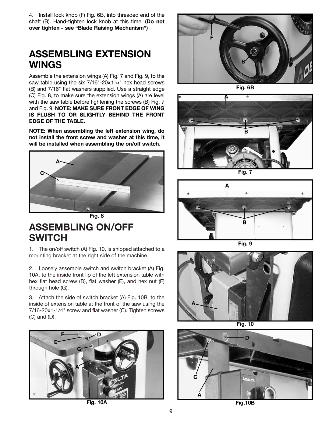
4.Install lock knob (F) Fig. 6B, into threaded end of the shaft (B).
ASSEMBLING EXTENSION WINGS
Assemble the extension wings (A) Fig. 7 and Fig. 9, to the saw table using the six
(B)and 7/16" flat washers supplied. Use a straight edge
(C)Fig. 8, to make sure the extension wings (A) are level with the saw table before tightening the screws (B) Fig. 7 and Fig. 9. NOTE: MAKE SURE FRONT EDGE OF WING
IS FLUSH TO OR SLIGHTLY BEHIND THE FRONT EDGE OF THE TABLE.
NOTE: When assembling the left extension wing, do not install the front screw and washer at this time, it will be installed when assembling the on/off switch.
A![]()
C
Fig. 8
ASSEMBLING ON/OFF SWITCH
1.The on/off switch (A) Fig. 10, is shipped attached to a mounting bracket at the right side of the machine.
2.Loosely assemble switch and switch bracket (A) Fig. 10A, to the inside front lip of the left extension table with hex flat head screw (D), flat washer (E), and hex nut (F) through hole (G).
3.Attach the side of switch bracket (A) Fig. 10B, to the inside of extension table at the front of the saw using the
(C) and (D).
F![]()
![]() D
D
E
G![]()
A
Fig. 10A
F
B
Fig. 6B
A |
B |
Fig. 7
A
B
Fig. 9
A
Fig. 10
D
C
A
Fig.10B
9