Delta 36-841 instruction manual

Models: 36-841

1 40
Download 40 pages 4.79 Kb
Page 17
Image 17

F

Fig. 49

3.Insert two 3/8-24x1" hex head bolts into the two holes (F) Fig. 49, in the front of saw table and place flat washer and nut onto bolt from underneath the saw table. Screw bolts into nuts two full turns, leaving bolt head extended approximately 1/2" from the table. Note: Make sure to use only the two holes shown at (F).

4.Insert two 1/4-20x3/4" hex head bolt (E) Fig. 50 into the front support of the extension table and place flat washer and nut onto bolt from underneath the extension table. Screw bolt into nut two complete turns, leaving bolt head extended approximately 1/4" from the extension table.

5.Slide the T-SIot guide rail (A) Fig. 51, onto the hex head of the bolts partially inserted in step 3 and 4 above.

Note: The bolt heads on the saw table slide into the upper t-slot (B) Fig. 51 and the bolt head on the extension table slide into the lower t-slot (C) Fig. 52.

6.Slide the guide rail along until the “0” on the Unifence scale is aligned with the right edge of the saw table. Snug the hex nuts on the saw and extension table but do not tighten at this time.

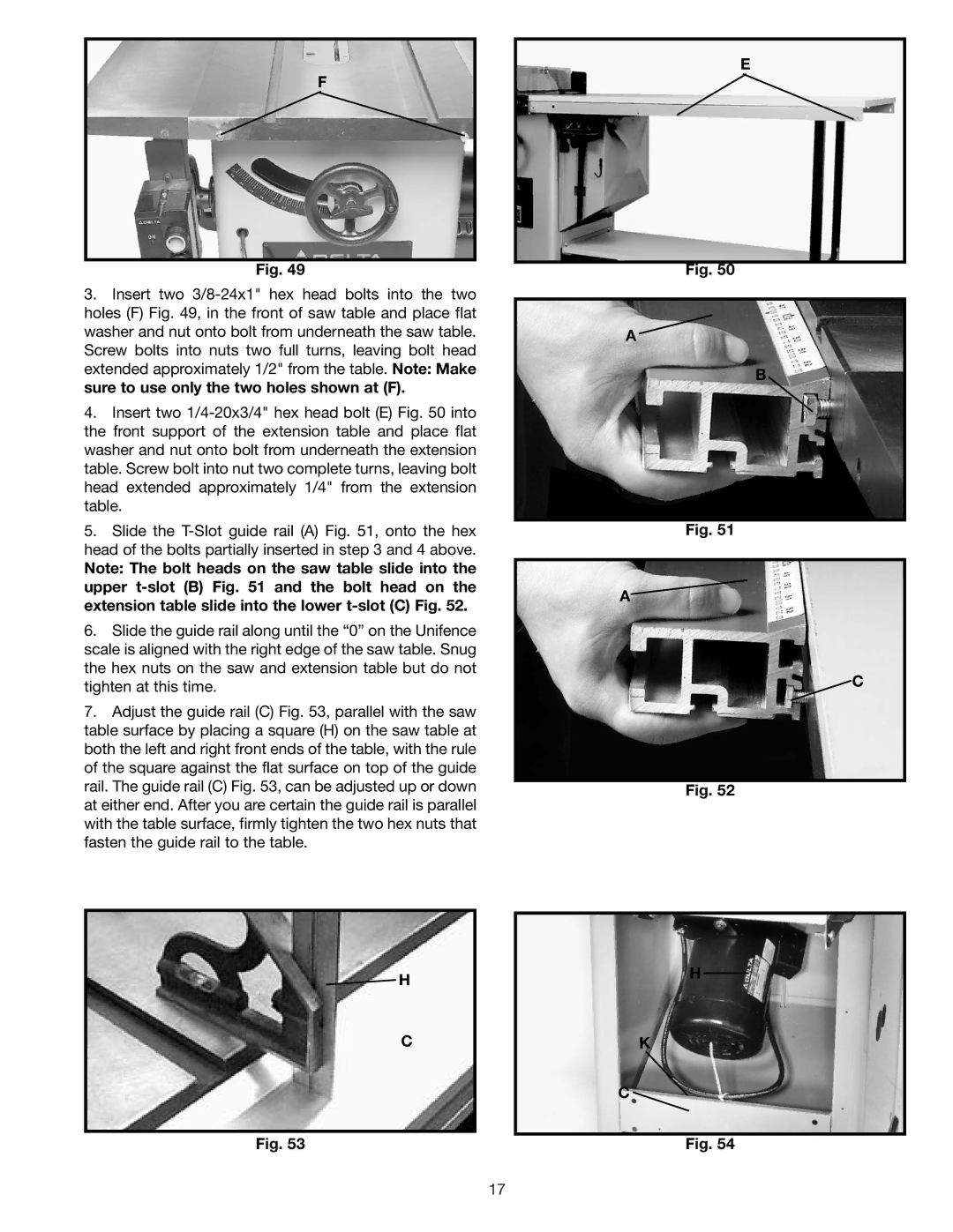
7.Adjust the guide rail (C) Fig. 53, parallel with the saw table surface by placing a square (H) on the saw table at both the left and right front ends of the table, with the rule of the square against the flat surface on top of the guide rail. The guide rail (C) Fig. 53, can be adjusted up or down at either end. After you are certain the guide rail is parallel with the table surface, firmly tighten the two hex nuts that fasten the guide rail to the table.

H

C

Fig. 53

E

Fig. 50

A

B

Fig. 51

A

C

Fig. 52

H

K

C

Fig. 54

17

Page 17
Image 17
Delta 36-841 instruction manual