Delta 36-841 instruction manual Assembling Guide Rails

Models: 36-841

1 40
Download 40 pages 4.79 Kb
Page 25
Image 25

ASSEMBLY INSTRUCTIONS FOR MODEL 78-995 50" COMMERCIAL BIESEMEYER FENCE SYSTEM

ASSEMBLING GUIDE RAILS

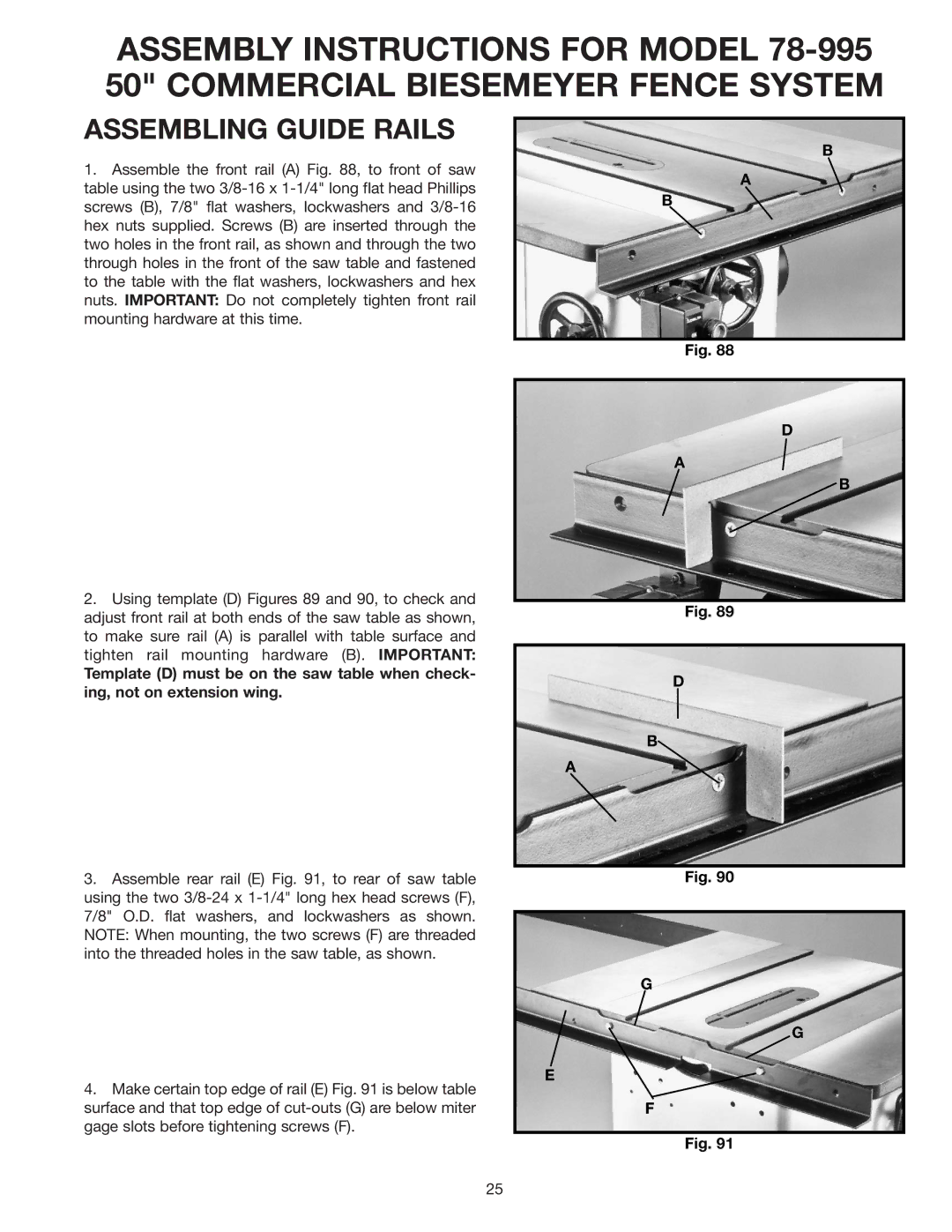
1.Assemble the front rail (A) Fig. 88, to front of saw table using the two 3/8-16 x 1-1/4" long flat head Phillips screws (B), 7/8" flat washers, lockwashers and 3/8-16 hex nuts supplied. Screws (B) are inserted through the two holes in the front rail, as shown and through the two through holes in the front of the saw table and fastened to the table with the flat washers, lockwashers and hex nuts. IMPORTANT: Do not completely tighten front rail mounting hardware at this time.

2.Using template (D) Figures 89 and 90, to check and adjust front rail at both ends of the saw table as shown, to make sure rail (A) is parallel with table surface and tighten rail mounting hardware (B). IMPORTANT:

Template (D) must be on the saw table when check- ing, not on extension wing.

3.Assemble rear rail (E) Fig. 91, to rear of saw table using the two 3/8-24 x 1-1/4" long hex head screws (F), 7/8" O.D. flat washers, and lockwashers as shown. NOTE: When mounting, the two screws (F) are threaded into the threaded holes in the saw table, as shown.

4.Make certain top edge of rail (E) Fig. 91 is below table surface and that top edge of cut-outs (G) are below miter gage slots before tightening screws (F).

B

A

B

Fig. 88

D

A

B

Fig. 89

D

B

A

Fig. 90

G

G

E

F

Fig. 91

25

Page 25
Image 25
Delta 36-841 instruction manual Assembling Guide Rails