C
A
B
Fig. 66
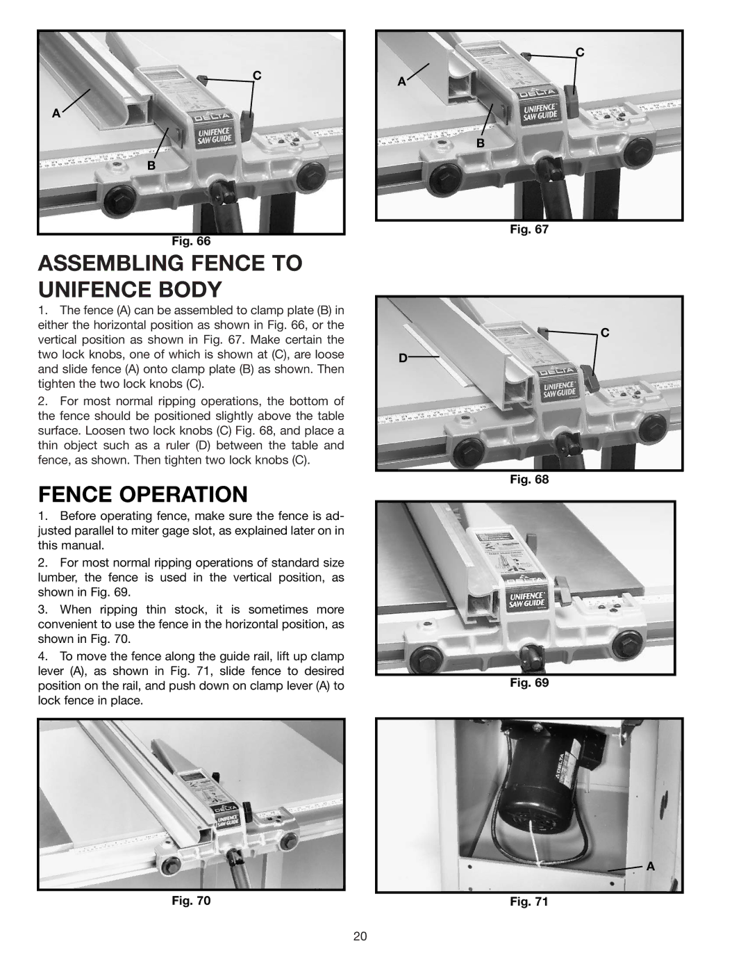
ASSEMBLING FENCE TO UNIFENCE BODY
1.The fence (A) can be assembled to clamp plate (B) in either the horizontal position as shown in Fig. 66, or the vertical position as shown in Fig. 67. Make certain the two lock knobs, one of which is shown at (C), are loose and slide fence (A) onto clamp plate (B) as shown. Then tighten the two lock knobs (C).
2.For most normal ripping operations, the bottom of the fence should be positioned slightly above the table surface. Loosen two lock knobs (C) Fig. 68, and place a thin object such as a ruler (D) between the table and fence, as shown. Then tighten two lock knobs (C).
FENCE OPERATION
1.Before operating fence, make sure the fence is ad- justed parallel to miter gage slot, as explained later on in this manual.
2.For most normal ripping operations of standard size lumber, the fence is used in the vertical position, as shown in Fig. 69.
3.When ripping thin stock, it is sometimes more convenient to use the fence in the horizontal position, as shown in Fig. 70.
4.To move the fence along the guide rail, lift up clamp lever (A), as shown in Fig. 71, slide fence to desired position on the rail, and push down on clamp lever (A) to lock fence in place.
Fig. 70
C
A
B
Fig. 67
![]() C
C
D
Fig. 68
Fig. 69
![]() A
A
Fig. 71
20