9.Place a ¼" flat washer and then a spacer (P) onto the
(I) Fig. 37.
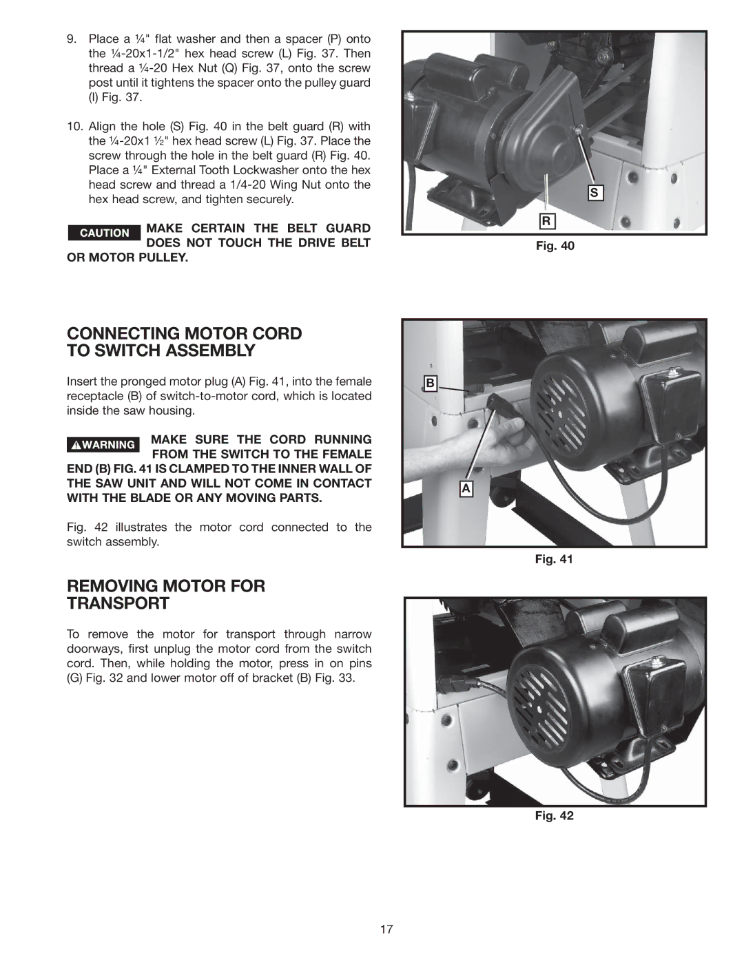
10.Align the hole (S) Fig. 40 in the belt guard (R) with the
MAKE CERTAIN THE BELT GUARD DOES NOT TOUCH THE DRIVE BELT
OR MOTOR PULLEY.
CONNECTING MOTOR CORD TO SWITCH ASSEMBLY
Insert the pronged motor plug (A) Fig. 41, into the female receptacle (B) of
MAKE SURE THE CORD RUNNING
FROM THE SWITCH TO THE FEMALE END (B) FIG. 41 IS CLAMPED TO THE INNER WALL OF THE SAW UNIT AND WILL NOT COME IN CONTACT WITH THE BLADE OR ANY MOVING PARTS.
Fig. 42 illustrates the motor cord connected to the switch assembly.
REMOVING MOTOR FOR
TRANSPORT
To remove the motor for transport through narrow doorways, first unplug the motor cord from the switch cord. Then, while holding the motor, press in on pins
(G) Fig. 32 and lower motor off of bracket (B) Fig. 33.
S
R
Fig. 40
B
A
Fig. 41
Fig. 42
17
