Delta 36-978 instruction manual Mobile Base And Stand Assembly

Models: 36-978

1 37
Download 37 pages 14.28 Kb
Page 11
Image 11
MOBILE BASE AND STAND ASSEMBLY

FOR YOUR OWN SAFETY, DO NOT CONNECT MACHINE TO POWER SOURCE UNTIL MACHINE IS COMPLETELY ASSEMBLED AND YOU READ AND UNDERSTAND THE INSTRUCTION MANUAL.

MOBILE BASE AND STAND ASSEMBLY

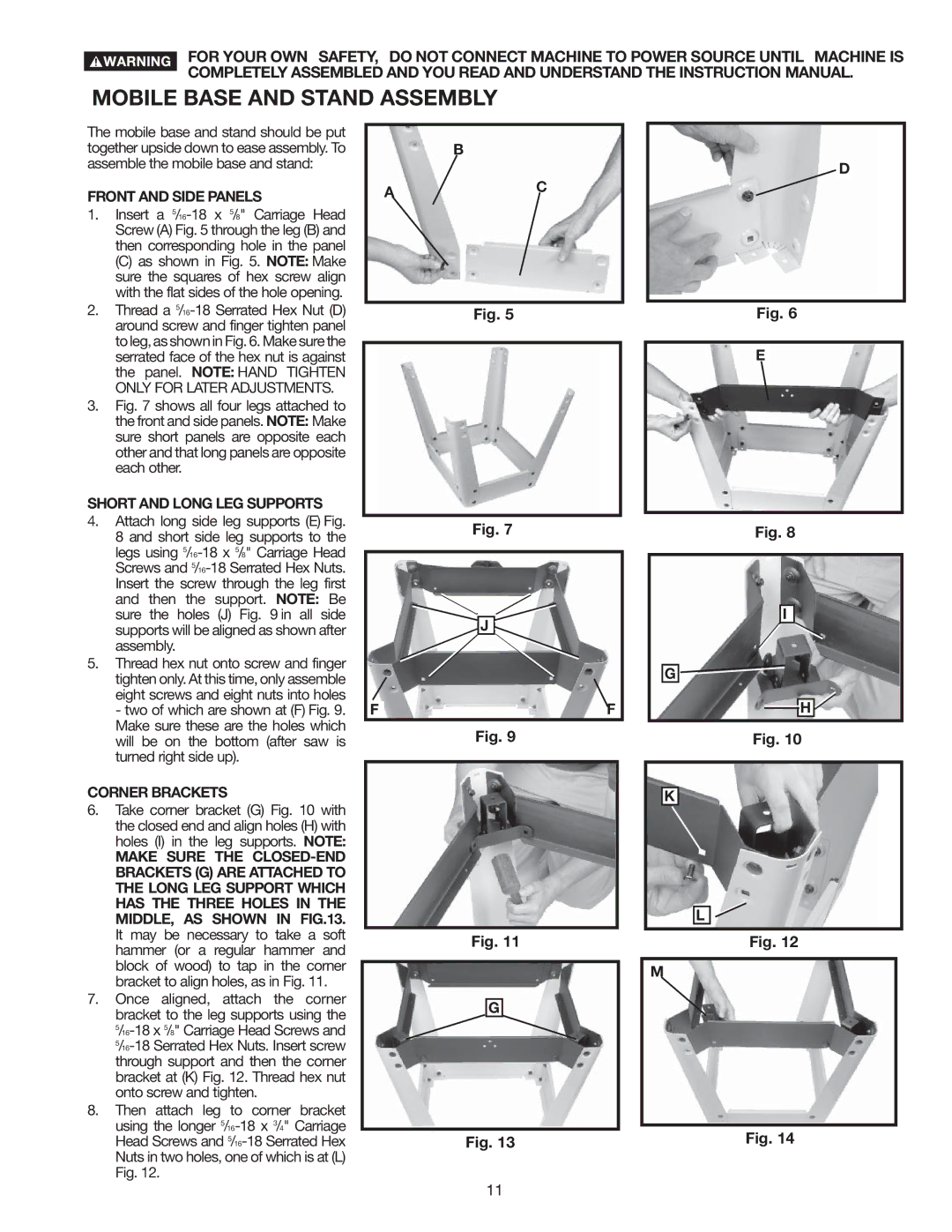
The mobile base and stand should be put together upside down to ease assembly. To assemble the mobile base and stand:

FRONT AND SIDE PANELS

1.Insert a 5/16-18 x 5/8" Carriage Head Screw (A) Fig. 5 through the leg (B) and then corresponding hole in the panel

(C)as shown in Fig. 5. NOTE: Make sure the squares of hex screw align with the flat sides of the hole opening.

2.Thread a 5/16-18 Serrated Hex Nut (D) around screw and finger tighten panel to leg, as shown in Fig. 6. Make sure the serrated face of the hex nut is against the panel. NOTE: HAND TIGHTEN ONLY FOR LATER ADJUSTMENTS.

3.Fig. 7 shows all four legs attached to the front and side panels. NOTE: Make sure short panels are opposite each other and that long panels are opposite each other.

SHORT AND LONG LEG SUPPORTS

4.Attach long side leg supports (E) Fig. 8 and short side leg supports to the legs using 5/16-18 x 5/8" Carriage Head Screws and 5/16-18 Serrated Hex Nuts. Insert the screw through the leg first and then the support. NOTE: Be sure the holes (J) Fig. 9 in all side supports will be aligned as shown after assembly.

5.Thread hex nut onto screw and finger tighten only. At this time, only assemble eight screws and eight nuts into holes - two of which are shown at (F) Fig. 9. Make sure these are the holes which will be on the bottom (after saw is turned right side up).

CORNER BRACKETS

6.Take corner bracket (G) Fig. 10 with the closed end and align holes (H) with holes (I) in the leg supports. NOTE:

MAKE SURE THE CLOSED-END BRACKETS (G) ARE ATTACHED TO THE LONG LEG SUPPORT WHICH HAS THE THREE HOLES IN THE MIDDLE, AS SHOWN IN FIG.13. It may be necessary to take a soft hammer (or a regular hammer and block of wood) to tap in the corner bracket to align holes, as in Fig. 11.

7.Once aligned, attach the corner bracket to the leg supports using the

5/16-18 x 5/8" Carriage Head Screws and 5/16-18 Serrated Hex Nuts. Insert screw through support and then the corner bracket at (K) Fig. 12. Thread hex nut onto screw and tighten.

8.Then attach leg to corner bracket using the longer 5/16-18 x 3/4" Carriage Head Screws and 5/16-18 Serrated Hex Nuts in two holes, one of which is at (L) Fig. 12.

B

AC

Fig. 5

Fig. 7


J

F

F

Fig. 9

Fig. 11

G

Fig. 13

D

Fig. 6

E

Fig. 8

I

G

Manual backgroundH Manual background

Fig. 10

K

L Manual backgroundManual background

Fig. 12

M

Fig. 14

11

Page 11
Image 11
Delta 36-978 instruction manual Mobile Base And Stand Assembly