BLADE GUARD AND SPLITTER USE
 THE BLADE GUARD ASSEMBLY PROVIDED WITH DELTA SAWS, AS SHOWN IN FIG. S1 MUST BE USED FOR ALL THROUGH-SAWING OPERATIONS. The splitter prevents the kerf from closing and binding the blade, causing kickback. The anti-kickback pawls (A) Fig. S1 prevent the workpiece and cut-off piece from being thrown back at the operator. The plastic guard prevents dust and debris from being thrown at the operator. To use the guard properly:
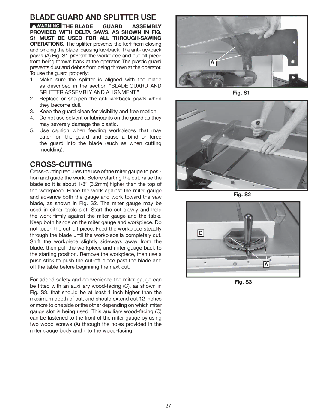
1.Make sure the splitter is aligned with the blade as described in the section “BLADE GUARD AND SPLITTER ASSEMBLY AND ALIGNMENT.”
2.Replace or sharpen the anti-kickback pawls when they become dull.
3.Keep the guard clean for visibility and free motion.
4.Do not use solvent or lubricants on the guard as they may severely damage the plastic.
5.Use caution when feeding workpieces that may catch on the guard and cause a bind or force the guard into the blade (such as when cutting moulding).
CROSS-CUTTING
Cross-cutting requires the use of the miter gauge to posi- tion and guide the work. Before starting the cut, raise the blade so it is about 1/8” (3.2mm) higher than the top of the workpiece. Place the work against the miter gauge and advance both the gauge and work toward the saw blade, as shown in Fig. S2. The miter gauge may be used in either table slot. Start the cut slowly and hold the work firmly against the miter gauge and the table. Keep both hands on the miter gauge and workpiece. Do not touch the cut-off piece. Feed the workpiece steadily through the blade until the workpiece is completely cut. Shift the workpiece slightly sideways away from the blade, then pull the workpiece and miter guage back to the starting position. Remove the workpiece, then use a push stick to push the cut-off piece past the blade and off the table before beginning the next cut.
For added safety and convenience the miter gauge can be fitted with an auxiliary wood-facing (C), as shown in Fig. S3, that should be at least 1 inch higher than the maximum depth of cut, and should extend out 12 inches or more to one side or the other depending on which miter gauge slot is being used. This auxiliary wood-facing (C) can be fastened to the front of the miter gauge by using two wood screws (A) through the holes provided in the miter gauge body and into the wood-facing.