BLADE TILTING
AND RAISING HANDWHEEL
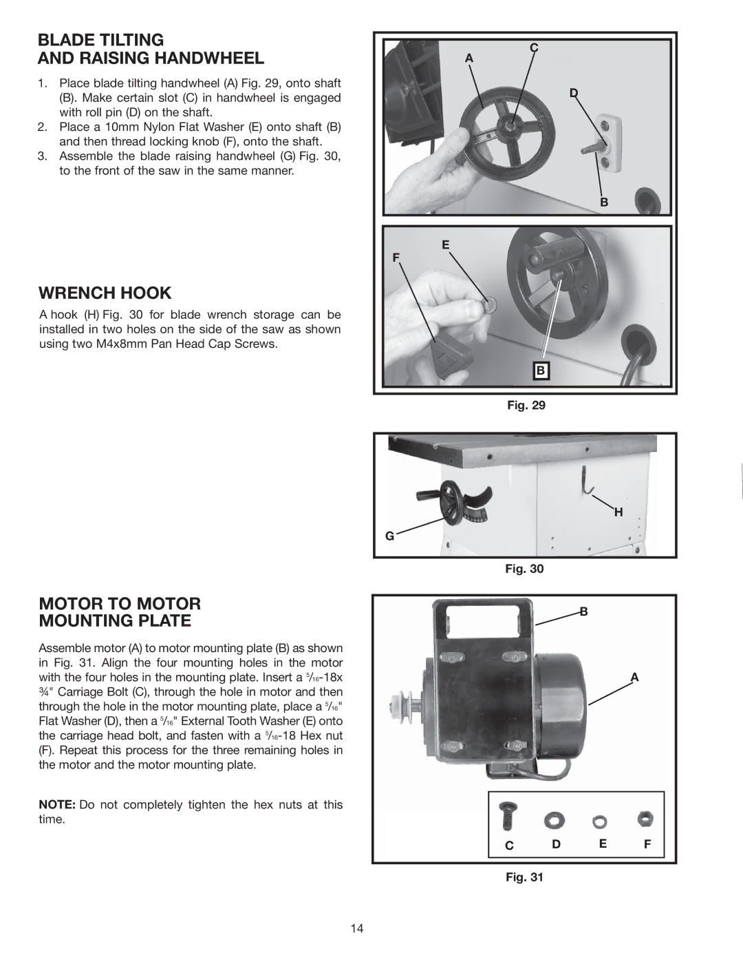
1.Place blade tilting handwheel (A) Fig. 29, onto shaft
(B). Make certain slot (C) in handwheel is engaged with roll pin (D) on the shaft.
2.Place a 10mm Nylon Flat Washer (E) onto shaft (B) and then thread locking knob (F), onto the shaft.
3.Assemble the blade raising handwheel (G) Fig. 30, to the front of the saw in the same manner.
WRENCH HOOK
A hook (H) Fig. 30 for blade wrench storage can be installed in two holes on the side of the saw as shown using two M4x8mm Pan Head Cap Screws.
C
A
D
B
E
F
B |
Fig. 29 |
MOTOR TO MOTOR
MOUNTING PLATE
Assemble motor (A) to motor mounting plate (B) as shown in Fig. 31. Align the four mounting holes in the motor with the four holes in the mounting plate. Insert a
(F). Repeat this process for the three remaining holes in the motor and the motor mounting plate.
NOTE: Do not completely tighten the hex nuts at this time.
G
H
Fig. 30
B
A
C D E F
Fig. 31
14
