9.Repeat for other similar corner bracket. These brackets, (G) Fig. 13 are where the rubber leveling feet will be installed.
10.The brackets with the open end, as shown at (M) Fig. 14, are attached in a similar manner as described in Steps 6 to 9. NOTE: MAKE SURE
THE OPEN END IS ALIGNED AS SHOWN IN FIGS. 14 AND 15.
THE WHEELS WILL BE INSTALL ED INSIDE THESE BRACKETS,
M
Fig. 17
AS SHOWN IN FIG. 20.
LEVELING FEET
Fig. 15
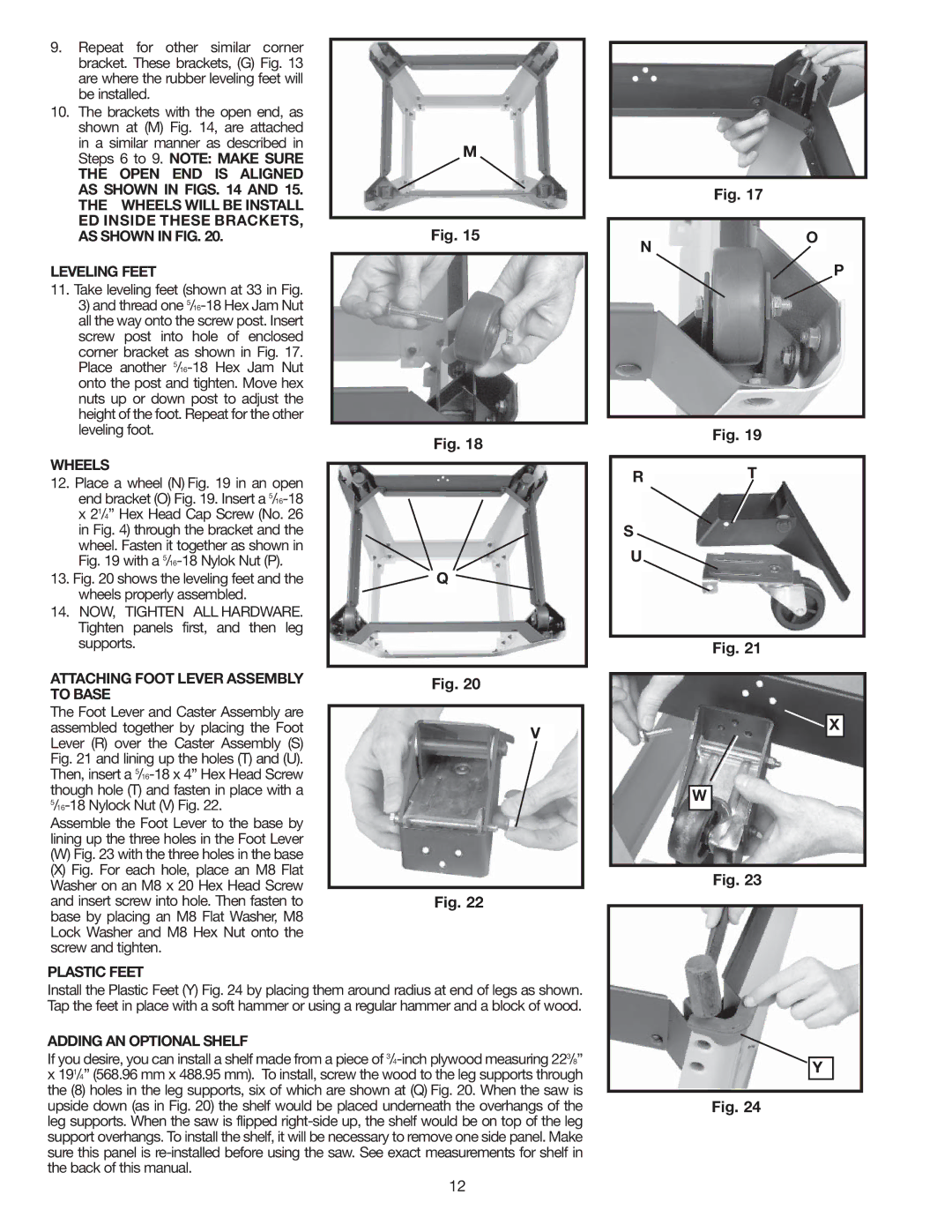
N
O
P
11.Take leveling feet (shown at 33 in Fig.
3)and thread one
WHEELS
12.Place a wheel (N) Fig. 19 in an open end bracket (O) Fig. 19. Insert a
13.Fig. 20 shows the leveling feet and the wheels properly assembled.
14.NOW, TIGHTEN ALL HARDWARE. Tighten panels first, and then leg supports.
ATTACHING FOOT LEVER ASSEMBLY TO BASE
The Foot Lever and Caster Assembly are assembled together by placing the Foot Lever (R) over the Caster Assembly (S) Fig. 21 and lining up the holes (T) and (U). Then, insert a
Assemble the Foot Lever to the base by lining up the three holes in the Foot Lever
(W)Fig. 23 with the three holes in the base
(X)Fig. For each hole, place an M8 Flat Washer on an M8 x 20 Hex Head Screw and insert screw into hole. Then fasten to base by placing an M8 Flat Washer, M8 Lock Washer and M8 Hex Nut onto the screw and tighten.
PLASTIC FEET
Fig. 18
Q
Fig. 20
V
Fig. 22
Fig. 19
RT
S
U
Fig. 21
X
W
Fig. 23
Install the Plastic Feet (Y) Fig. 24 by placing them around radius at end of legs as shown. Tap the feet in place with a soft hammer or using a regular hammer and a block of wood.
ADDING AN OPTIONAL SHELF
If you desire, you can install a shelf made from a piece of
Y
Fig. 24
12