Modbus TCP Remote I/O Communication Module
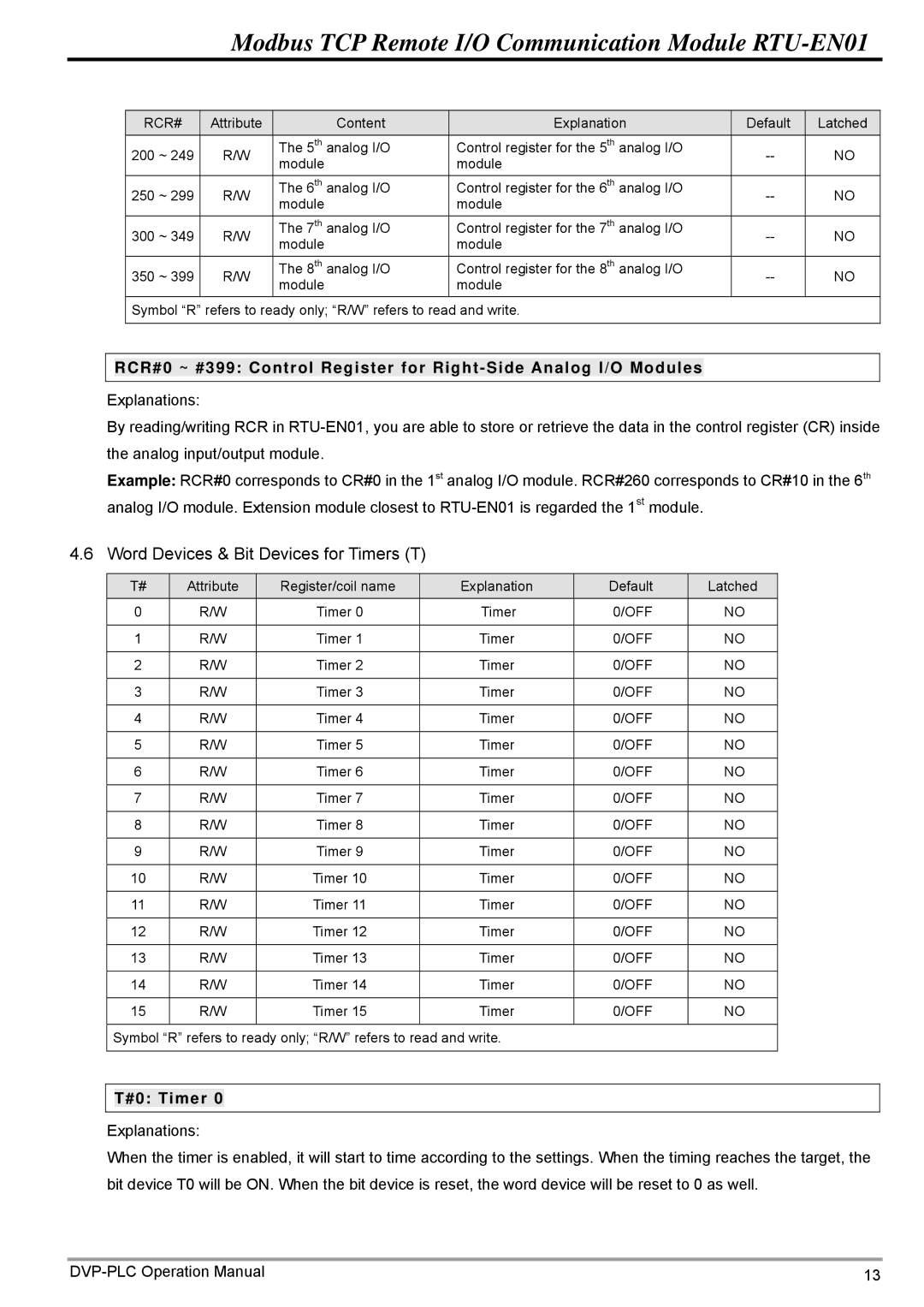
RCR# | Attribute |
| Content | Explanation | Default | Latched |
200 ~ 249 | R/W | The 5th | analog I/O | Control register for the 5th analog I/O | NO | |
module |
| module | ||||
|
|
|
|
| ||
250 ~ 299 | R/W | The 6th | analog I/O | Control register for the 6th analog I/O | NO | |
module |
| module | ||||
|
|
|
|
| ||
300 ~ 349 | R/W | The 7th | analog I/O | Control register for the 7th analog I/O | NO | |
module |
| module | ||||
|
|
|
|
| ||
350 ~ 399 | R/W | The 8th | analog I/O | Control register for the 8th analog I/O | NO | |
module |
| module | ||||
|
|
|
|
|
Symbol “R” refers to ready only; “R/W” refers to read and write.
RCR#0 ~ #399: Control Register for
Explanations:
By reading/writing RCR in
Example: RCR#0 corresponds to CR#0 in the 1st analog I/O module. RCR#260 corresponds to CR#10 in the 6th analog I/O module. Extension module closest to
4.6 Word Devices & Bit Devices for Timers (T)
T# | Attribute | Register/coil name | Explanation |
0 | R/W | Timer 0 | Timer |
|
|
|
|
1 | R/W | Timer 1 | Timer |
|
|
|
|
2 | R/W | Timer 2 | Timer |
|
|
|
|
3 | R/W | Timer 3 | Timer |
|
|
|
|
4 | R/W | Timer 4 | Timer |
|
|
|
|
5 | R/W | Timer 5 | Timer |
|
|
|
|
6 | R/W | Timer 6 | Timer |
|
|
|
|
7 | R/W | Timer 7 | Timer |
|
|
|
|
8 | R/W | Timer 8 | Timer |
|
|
|
|
9 | R/W | Timer 9 | Timer |
|
|
|
|
10 | R/W | Timer 10 | Timer |
|
|
|
|
11 | R/W | Timer 11 | Timer |
|
|
|
|
12 | R/W | Timer 12 | Timer |
|
|
|
|
13 | R/W | Timer 13 | Timer |
|
|
|
|
14 | R/W | Timer 14 | Timer |
|
|
|
|
15 | R/W | Timer 15 | Timer |
|
|
|
|
Symbol “R” refers to ready only; “R/W” refers to read and write.
Default 0/OFF 0/OFF 0/OFF 0/OFF 0/OFF 0/OFF 0/OFF 0/OFF 0/OFF 0/OFF 0/OFF 0/OFF 0/OFF 0/OFF 0/OFF 0/OFF
Latched
NO
NO
NO
NO
NO
NO
NO
NO
NO
NO
NO
NO
NO
NO
NO
NO
T#0: Timer 0
Explanations:
When the timer is enabled, it will start to time according to the settings. When the timing reaches the target, the bit device T0 will be ON. When the bit device is reset, the word device will be reset to 0 as well.
13 |