AVR-4802 specifications
The Denon AVR-4802 is a premium home theater receiver that has garnered a reputation for delivering exceptional audio and video performance. Launched as part of Denon's celebrated line of A/V receivers, the AVR-4802 exemplifies the brand's commitment to quality and innovation in the realm of home entertainment.One of the key features of the AVR-4802 is its robust amplification capability. It provides a powerful 110 watts per channel, allowing users to enjoy a dynamic and impactful soundstage. The receiver is equipped with multiple channels, which facilitates a fully immersive surround sound experience, accommodating various speaker configurations, including traditional 5.1 and more advanced setups like 7.1 surround sound.
The AVR-4802 incorporates cutting-edge surround sound processing technologies, including Dolby Digital and DTS, ensuring high-fidelity audio reproduction for both movies and music. Additionally, it supports 24-bit/192kHz audio playback, which enhances the detail and clarity of sound, making it suitable for both casual listeners and audiophiles.
In terms of video capabilities, the AVR-4802 supports high-quality video formats, including progressive scan for smoother images, and it features multiple video inputs, including S-Video and composite connections. This versatility allows users to connect various devices, such as DVD players and gaming consoles, simplifying the integration of a comprehensive home theater system.
The receiver also comes with advanced DSP (Digital Signal Processing) algorithms that optimize audio output based on the environment, providing an improved listening experience regardless of the room's acoustics. This feature further enhances the AVR-4802's appeal to home theater enthusiasts looking for customizability.
Another outstanding characteristic of the AVR-4802 is its user-friendly interface, featuring a comprehensive on-screen display that simplifies setup and operation. It includes a remote control that offers convenient access to all functionalities, making navigation through various settings intuitive.
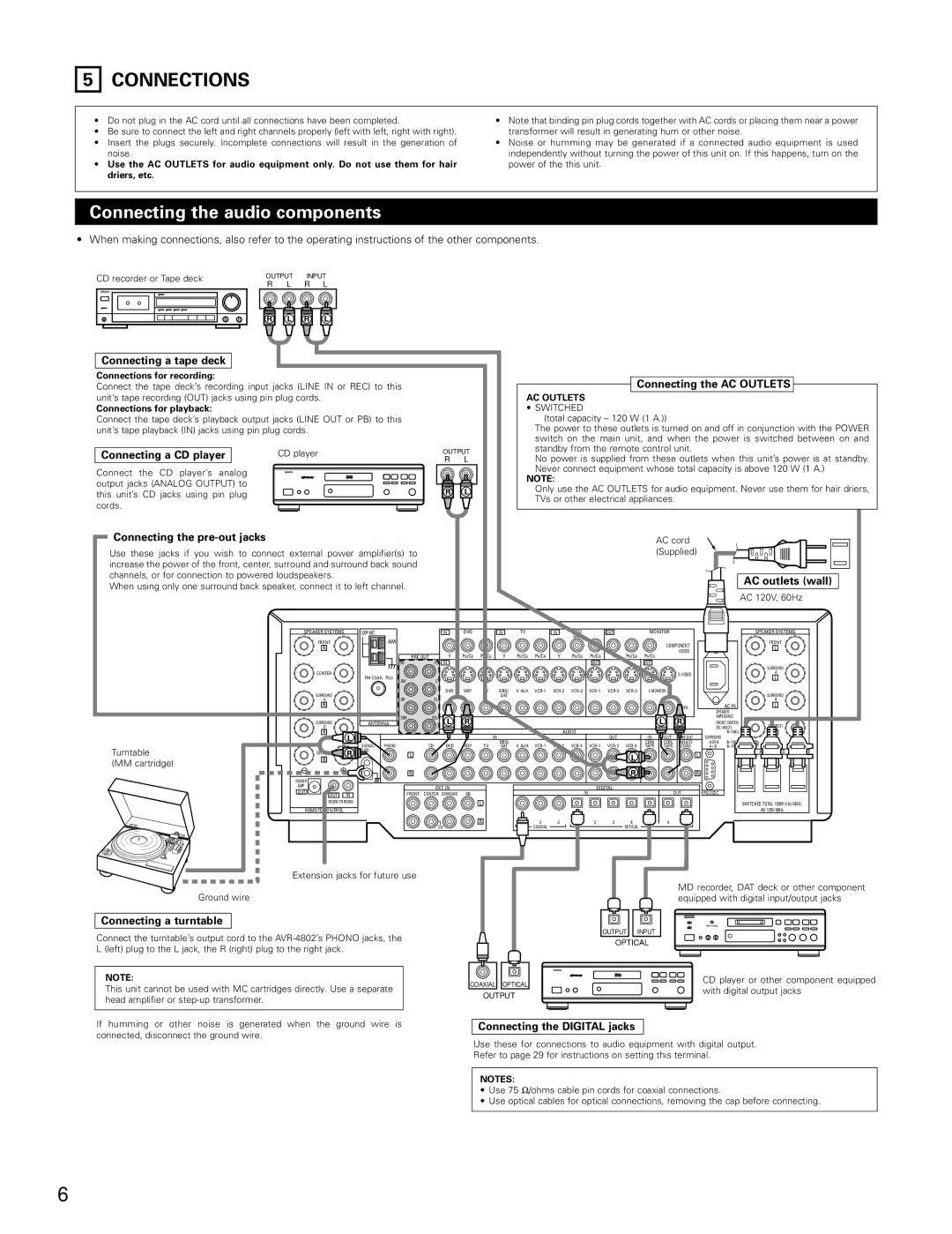
Additionally, the AVR-4802 is equipped with multiple digital and analog inputs, which provides flexibility in connecting other audio and video components. The receiver's build quality is also noteworthy, reflecting Denon's attention to detail, ensuring durability and performance.
Overall, the Denon AVR-4802 is a well-rounded A/V receiver that combines power, advanced technologies, and user-friendly features to create an ideal centerpiece for any home theater system, offering an unparalleled entertainment experience for users who appreciate high-quality sound and video.