VENTING INSTALLATION
Continued
In each case the offsets must be supported and firestops must be positioned wherever the vent must pass through a
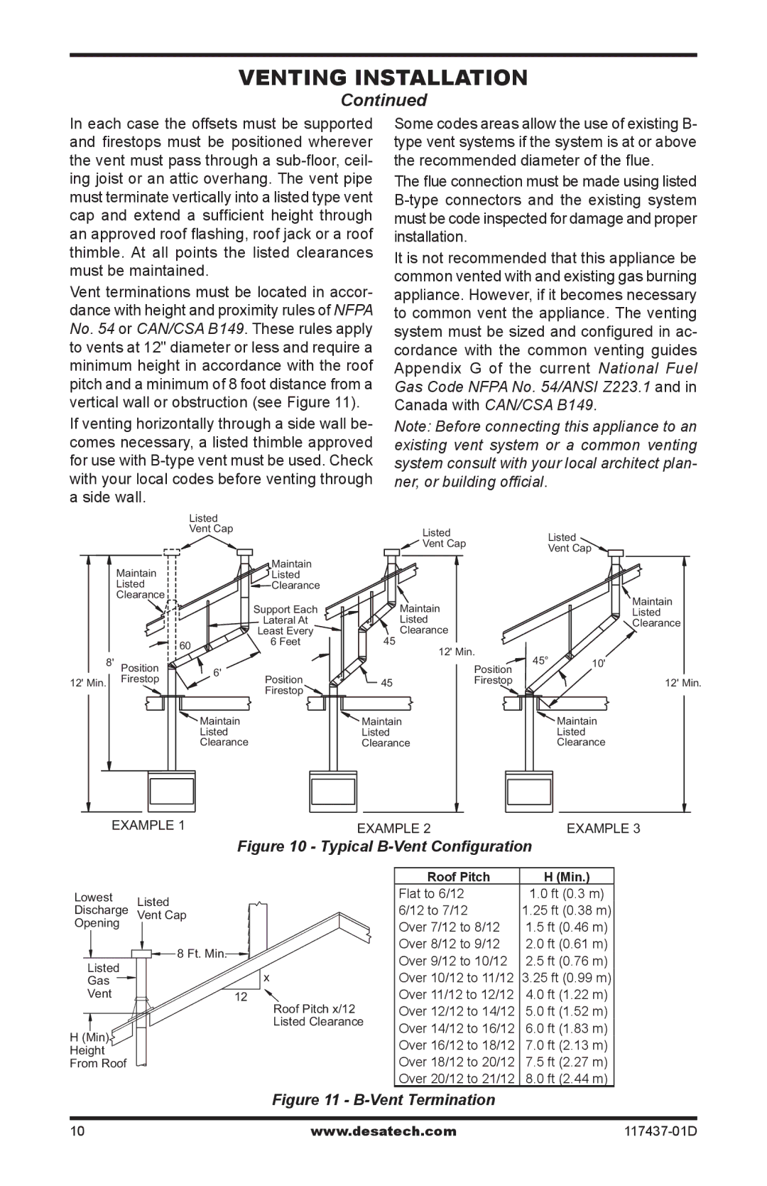
Vent terminations must be located in accor- dance with height and proximity rules of NFPA No. 54 or CAN/CSA B149. These rules apply to vents at 12" diameter or less and require a minimum height in accordance with the roof pitch and a minimum of 8 foot distance from a vertical wall or obstruction (see Figure 11).
If venting horizontally through a side wall be- comes necessary, a listed thimble approved for use with
Some codes areas allow the use of existing B- type vent systems if the system is at or above the recommended diameter of the flue.
The flue connection must be made using listed
It is not recommended that this appliance be common vented with and existing gas burning appliance. However, if it becomes necessary to common vent the appliance. The venting system must be sized and configured in ac- cordance with the common venting guides Appendix G of the current National Fuel Gas Code NFPA No. 54/ANSI Z223.1 and in Canada with CAN/CSA B149.
Note: Before connecting this appliance to an existing vent system or a common venting system consult with your local architect plan- ner, or building official.
|
| Listed |
|
|
|
|
|
|
| Vent Cap |
| Listed |
| Listed | |
|
|
|
|
| |||
|
|
|
| Vent Cap |
| ||
|
|
|
|
| Vent Cap | ||
|
|
|
|
|
| ||
| Maintain |
| Maintain |
|
|
|
|
|
| Listed |
|
|
|
| |
| Listed |
| Clearance |
|
|
|
|
| Clearance |
|
|
|
|
| Maintain |
|
|
| Support Each | Maintain |
|
| |
|
|
|
|
| Listed | ||
|
|
| Lateral At | Listed |
|
| Clearance |
|
|
| Least Every | Clearance |
|
|
|
|
| 60 | 6 Feet | 45 |
|
|
|
|
|
| 12' Min. |
|
| ||
8' Position |
|
| 45° | 10' | |||
|
|
| Position | ||||
6' |
|
|
| ||||
12' Min. | Firestop | Position | 45 | Firestop |
| 12' Min. | |
|
| ||||||
|
| Firestop |
|
| |||
|
|
|
|
|
|
| |
|
| Maintain |
| Maintain |
|
| Maintain |
|
| Listed |
| Listed |
|
| Listed |
|
| Clearance |
| Clearance |
|
| Clearance |
EXAMPLE 1 | EXAMPLE 2 | EXAMPLE 3 |
| Figure 10 - Typical |
|
Lowest Listed
Discharge Vent Cap
Opening
| 8 Ft. Min. |
Listed |
|
Gas |
|
Vent | 12 |
H(Min) Height From Roof
| Roof Pitch | H (Min.) |
| Flat to 6/12 | 1.0 ft (0.3 m) |
| 6/12 to 7/12 | 1.25 ft (0.38 m) |
| Over 7/12 to 8/12 | 1.5 ft (0.46 m) |
| Over 8/12 to 9/12 | 2.0 ft (0.61 m) |
| Over 9/12 to 10/12 | 2.5 ft (0.76 m) |
x | Over 10/12 to 11/12 | 3.25 ft (0.99 m) |
Roof Pitch x/12 | Over 11/12 to 12/12 | 4.0 ft (1.22 m) |
Over 12/12 to 14/12 | 5.0 ft (1.52 m) | |
Listed Clearance | Over 14/12 to 16/12 | 6.0 ft (1.83 m) |
| ||
| Over 16/12 to 18/12 | 7.0 ft (2.13 m) |
| Over 18/12 to 20/12 | 7.5 ft (2.27 m) |
| Over 20/12 to 21/12 | 8.0 ft (2.44 m) |
Figure 11 - B-Vent Termination
10 | www.desatech.com |