INSTALLING OPTIONAL CONTROLS
Continued
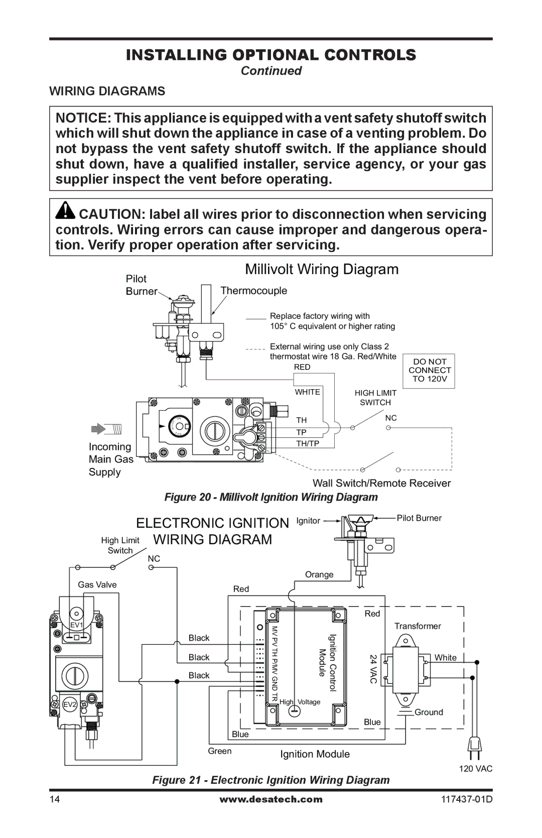
WIRING DIAGRAMS
NOTICE: This appliance is equipped with a vent safety shutoff switch which will shut down the appliance in case of a venting problem. Do not bypass the vent safety shutoff switch. If the appliance should shut down, have a qualified installer, service agency, or your gas supplier inspect the vent before operating.
![]() CAUTION: label all wires prior to disconnection when servicing controls. Wiring errors can cause improper and dangerous opera- tion. Verify proper operation after servicing.
CAUTION: label all wires prior to disconnection when servicing controls. Wiring errors can cause improper and dangerous opera- tion. Verify proper operation after servicing.
Pilot
Millivolt Wiring Diagram
Burner  Thermocouple
Incoming
Main Gas
Supply
| ON |
LO | T |
| |
I |
|
P | |
| F FO |
Replace factory wiring with
105° C equivalent or higher rating
External wiring use only Class 2 thermostat wire 18 Ga. Red/White
RED |
|
WHITE | HIGH LIMIT |
| SWITCH |
TH | NC |
TP |
|
TH/TP |
|
DO NOT
CONNECT
TO 120V
Wall Switch/Remote Receiver
Figure 20 - Millivolt Ignition Wiring Diagram
ELECTRONIC IGNITION Ignitor  High Limit WIRING DIAGRAM
Switch
NC
|
|
| Orange |
Gas Valve |
| Red |
|
|
|
| |
EV1 |
| MV PV THP/MVGND |
|
| Black | IgnitionControl Module | |
| Black | ||
| Black |
|
|
EV2 |
| TR | High Voltage |
|
| ||
|
|
| |
|
| Blue |
|
| Green |
| Ignition Module |
![]() Pilot Burner
Pilot Burner
Red
| Transformer |
24 VAC | White |
| |
| Ground |
Blue |
|
120 VAC
Figure 21 - Electronic Ignition Wiring Diagram
14 | www.desatech.com |