Pre-Installation Preparation
| Continued | ||
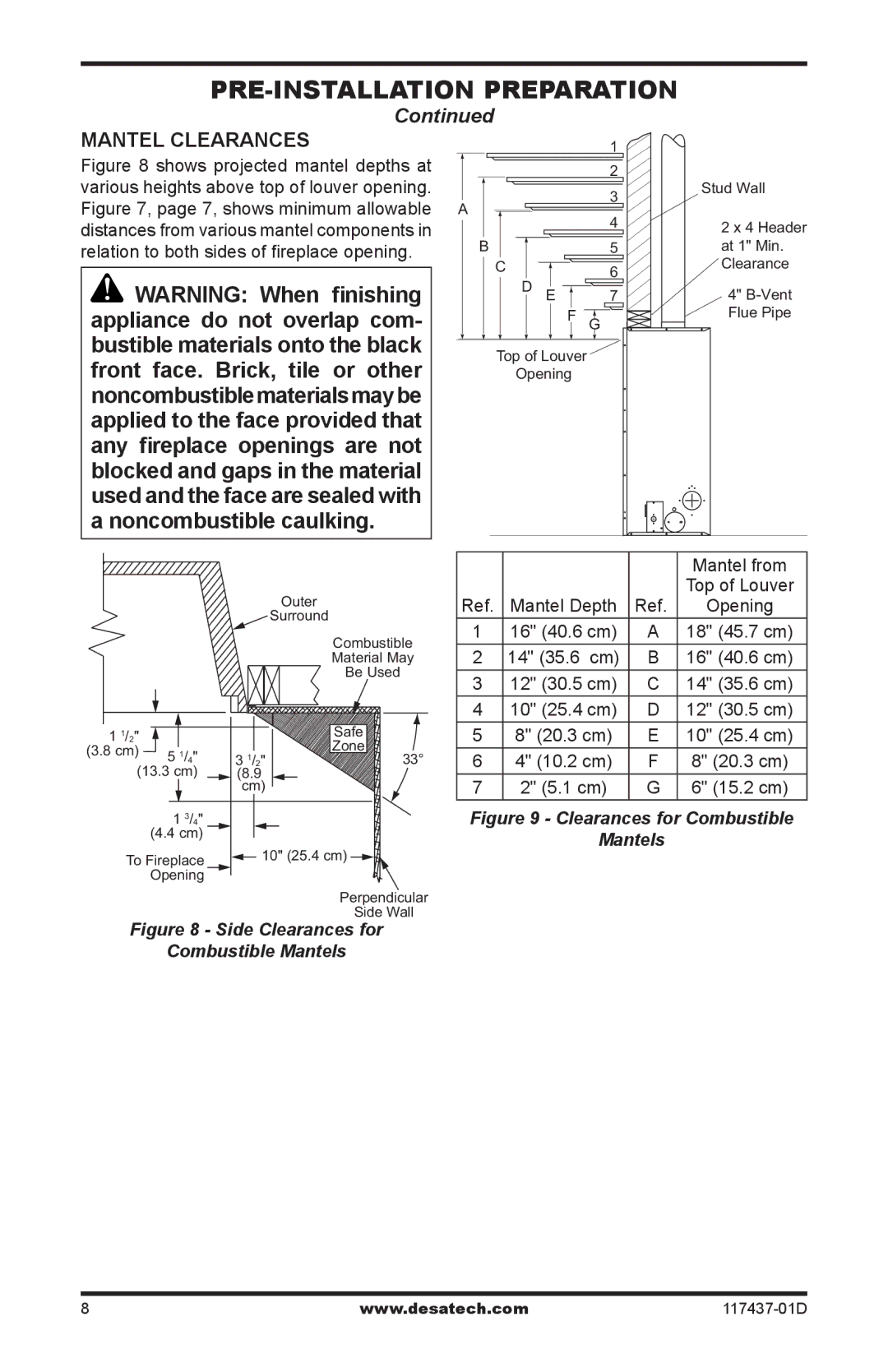
MANTEL CLEARANCES |
|
| 1 |
Figure 8 shows projected mantel depths at various heights above top of louver opening. Figure 7, page 7, shows minimum allowable distances from various mantel components in relation to both sides of fireplace opening.
![]() WARNING: When finishing appliance do not overlap com- bustible materials onto the black front face. Brick, tile or other noncombustiblematerialsmaybe applied to the face provided that any fireplace openings are not blocked and gaps in the material used and the face are sealed with a noncombustible caulking.
WARNING: When finishing appliance do not overlap com- bustible materials onto the black front face. Brick, tile or other noncombustiblematerialsmaybe applied to the face provided that any fireplace openings are not blocked and gaps in the material used and the face are sealed with a noncombustible caulking.
|
|
|
|
|
|
|
|
|
|
|
|
|
|
| 2 | |||
|
|
|
|
|
|
|
|
|
|
|
|
|
|
| 3 | |||
A |
|
|
|
|
|
|
|
|
|
|
|
| ||||||
|
|
|
|
|
|
|
|
|
|
|
| 4 | ||||||
|
|
|
|
|
|
|
|
|
|
|
|
|
|
| ||||
|
|
|
|
|
|
|
|
|
|
|
|
|
|
|
| |||
|
| B |
|
|
|
|
|
|
|
|
|
| 5 | |||||
|
|
|
|
|
|
|
|
|
|
|
|
|
|
|
|
|
|
|
|
|
|
| C |
|
|
|
|
|
|
| 6 | ||||||
|
|
|
|
|
| |||||||||||||
|
|
|
|
|
|
|
|
|
|
|
|
|
|
| ||||
|
|
|
|
|
|
| D E |
|
|
| 7 | |||||||
|
|
|
|
|
|
|
|
|
|
|
|
|
|
|
|
|
| |
|
|
|
|
|
|
|
|
|
|
|
| F |
|
| ||||
|
|
|
|
|
|
|
|
|
|
|
| G | ||||||
|
|
|
|
|
|
|
|
|
|
|
|
|
| |||||
|
|
|
|
|
|
|
|
|
|
|
|
|
|
|
|
|
|
|
Top of Louver
Opening
Stud Wall
2 x 4 Header
at 1" Min.
Clearance
4" B-Vent
Flue Pipe
|
|
|
|
|
| Mantel from |
|
| Outer |
|
|
| Top of Louver |
|
| Ref. | Mantel Depth | Ref. | Opening | |
|
| Surround | 1 | 16" (40.6 cm) | A | 18" (45.7 cm) |
|
| Combustible | ||||
|
| 2 | 14" (35.6 cm) | B | 16" (40.6 cm) | |
|
| Material May | ||||
|
| Be Used | 3 | 12" (30.5 cm) | C | 14" (35.6 cm) |
|
|
| ||||
|
|
| 4 | 10" (25.4 cm) | D | 12" (30.5 cm) |
1 1/2" |
| Safe | 5 | 8" (20.3 cm) | E | 10" (25.4 cm) |
(3.8 cm) 5 1/4" |
| Zone |
|
|
|
|
3 1/2" | 33° | 6 | 4" (10.2 cm) | F | 8" (20.3 cm) | |
(13.3 cm) | (8.9 |
| 7 | 2" (5.1 cm) | G | 6" (15.2 cm) |
| cm) |
| ||||
1 3/4" |
|
| Figure 9 - Clearances for Combustible | |||
(4.4 cm) |
|
|
| Mantels |
| |
| 10" (25.4 cm) |
|
| |||
To Fireplace |
|
|
|
| ||
Opening |
|
|
|
|
|
|
|
| Perpendicular |
|
|
|
|
|
| Side Wall |
|
|
|
|
Figure 8 - Side Clearances for |
|
|
|
| ||
Combustible Mantels |
|
|
|
| ||
www.desatech.com117437-01D