INSTALLATION
Continued
Mantel Clearances for
Installation
If placing mantel above
NOTICE: Surface temperatures of adjacent walls and mantels be- come hot during operation. Walls and mantels above the firebox may become hot to the touch. If installed properly, these tem- peratures meet the requirement of the national product standard. Follow all minimum clearances shown in this manual.
NOTICE: If your installation does not meet the minimum clear- ances shown, you must do one
of the following:
•raise the mantel to an accept- able height
•remove the mantel
OPTIONAL MANTEL INSTALLATION
Note: Refer to instructions provided with the mantel for assembly instructions. Refer to the following instructions for system installation. Refer to instructions on page 6 for hood assembly. Blower accessory should be installed if it is being used (see Installing Optional Blower Accessory GA3450TA, page 13).
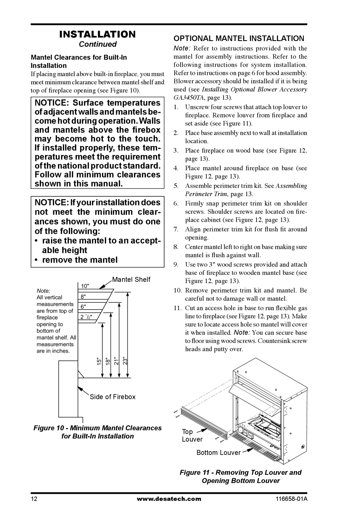
1. | Unscrew four screws that attach top louver to |
| fireplace. Remove louver from fireplace and |
| set aside (see Figure 11). |
2. | Place base assembly next to wall at installation |
| location. |
3. | Place fireplace on wood base (see Figure 12, |
| page 13). |
4. | Place mantel around fireplace on base (see |
| Figure 12, page 13). |
5. | Assemble perimeter trim kit. See Assembling |
| Perimeter Trim, page 13. |
6. | Firmly snap perimeter trim kit on shoulder |
| screws. Shoulder screws are located on fire- |
| place cabinet (see Figure 12, page 13). |
7. | Align perimeter trim kit for flush fit around |
| opening. |
8. | Center mantel left to right on base making sure |
| mantel is flush against wall. |
9. | Use two 3" wood screws provided and attach |
| base of fireplace to wooden mantel base (see |
Note: | 10" | |
8" | ||
All vertical |
measurements 6" are from top of
fireplace 2 1/2" opening to
bottom of mantel shelf. All measurements are in inches.
15" | 18" |
Mantel Shelf
21" |
| 23" |
| ||
|
|
|
Figure 12, page 13). |
10. Remove perimeter trim kit and mantel. Be |
careful not to damage wall or mantel. |
11. Cut an access hole in base to run flexible gas |
line to fireplace (see Figure 12, page 13). Make |
sure to locate access hole so mantel will cover |
it when installed. Note: You can secure base |
to floor using wood screws. Countersink screw |
heads and putty over. |
Side of Firebox
Figure 10 - Minimum Mantel Clearances
for
Top
Louver
Bottom Louver ![]()
Figure 11 - Removing Top Louver and Opening Bottom Louver
12 | www.desatech.com |