WHAT TO DO IF YOU SMELL GAS Do not try to light any appliance
116658-01A
TABLE OF CONTENTS
SAFETY INFORMATION
DANGER Carbon monoxide poisoning may lead to death
WARNING Any change to this fireplace or its controls can be dangerous
Continued
CONTROL ACCESSORIES
See Accessories, page
OPTIONAL REMOTE
fireplace. This prevents exces
diagrams or failure to use only
SAFETY PILOT
WARNING Always have
Unusually Tight Construction
b. weather stripping has been added on openable windows and doors and
PROVIDING ADEQUATE VENTILATION
Figure 3 - Assembling Hood
DETERMINING FRESH-AIR FLOW FOR FIREPLACE LOCATION
Confined and Unconfined Space
Determining if You Have a Confined or Unconfined Space
VENTILATION AIR
WARNING Never install the fireplace in a bedroom or bathroom
in a recreational vehicle
as a fireplace insert in high traffic areas in windy or drafty areas
CHECK GAS TYPE
INSTALLATION ITEMS
Before installing fireplace, make sure you have the items listed below
external regulator supplied by installer, for propane/LP units only
Figure 7 - Rough Opening for Installing in Wall
CAUTION If you install the fireplace in a home garage
locate fireplace where moving vehicle will not hit it
BUILT-IN FIREPLACE INSTALLATION
Figure 9 - Attaching Fireplace to Wall Studs
Note A qualified installer should make all electri- cal connections
4. If you have not installed hood, follow instruc- tions on page
7. Bend four nailing flanges on outer casing with pliers see Figure
OPTIONAL MANTEL INSTALLATION
of the following raise the mantel to an accept- able height
remove the mantel
INSTALLING OPTIONAL BLOWER ACCESSORY GA3450TA
Figure 12 - Attaching Brass Trim to Fireplace
Figure 13 - Assembling Brass Trim
Installing Blower Accessory
Screw Figure 16 - Installing Switch Plate to Remote/Blower Bracket
CAUTION Verify proper op- eration after servicing
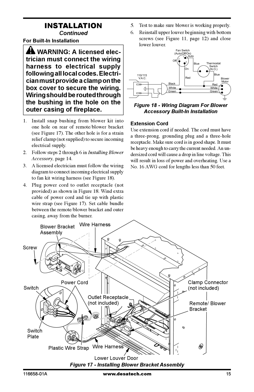
For Built-In Installation
Figure 17 - Installing Blower Bracket Assembly
Figure 18 - Wiring Diagram For Blower Accessory Built-In Installation
CONNECTING TO GAS SUPPLY
external to unit, for leaks after
installing or servicing. Correct
WARNING Test all gas piping
and connections, internal and
Figure 25 - Checking Gas Joints Natural Gas Only
PRESSURE TESTING GAS SUPPLY PIPING SYSTEM
PRESSURE TESTING FIREPLACE GAS CONNECTIONS
Figure 24 - Checking Gas Joints Propane/LP Only
OPTIONAL WALL MOUNTED THERMOSTAT - GWMT1
OPTIONAL WIRELESS HAND-HELD REMOTE CONTROL ACCESSORIES
Figure 26 - Disconnecting Wires From Control Valve
Figure 28 - Installing Remote Receiver
1. Remove jumper wire from control valve see Figure 26, page
7. Install the base onto the wall with the provided screws
Figure 30 - Connecting Wire Terminals
“W” and “R” OPTIONAL WALL SWITCH - GWMS2
Figure 34 - Installing Side Brick Liners
Figure 33 - Installing Rear Brick Liner
Figure 35 - Installing Log
Figure 36 - Installing Screen
FOR YOUR SAFETY READ BEFORE LIGHTING
OPERATING FIREPLACE
LIGHTING INSTRUCTIONS
OPTIONAL HAND-HELD REMOTE OPERATION
MANUAL LIGHTING PROCEDURE
2. If Using Optional Hand-Held Remote
TO TURN OFF GAS TO APPLIANCE
4. Press the POWER and LOCK buttons together to turn off the fireplace
Figure 40 - Setting the Selector Switch
Control Knob and Flame Adjustment Knob for Remote Operation
3. Press the POWER and LOCK buttons together to turn off the fireplace
PILOT FLAME PATTERN
OPTIONAL GWMS2 WALL MOUNTED SWITCH
see Troubleshooting, page
OPTIONAL GWMT1 WALL MOUNTED THERMOSTAT
BURNER INJECTOR HOLDER AND PILOT AIR INLET HOLE
WARNING Turn off fireplace and let cool before cleaning
CONTINUED
BURNER FLAME PATTERN
Figure 49 - Pilot Inlet Air Hole Natural Gas
LOG SET
CABINET
Figure 48 - Pilot Inlet Air Hole Propane/LP Gas
REMEDY
TROUBLESHOOTING
OBSERVED PROBLEM
POSSIBLE CAUSE
OBSERVED PROBLEM POSSIBLE CAUSE
see Cleaning and Mainte
WARNING If you smell gas Shut off gas supply
Do not try to light any appliance
If you cannot reach your gas supplier, call the fire department
CDCFNRA
SPECIFICATIONS
Remote-Ready Models
CDCFPRA
PARTS UNDER WARRANTY
REPLACEMENT PARTS
SERVICE HINTS
TECHNICAL SERVICE
FIREBOX CDCFNRA
PARTS
BREAKDOWN
ILLUSTRATED MODELS
FIREBOX MODELS CDCFNRA, CDCFPRA
PARTS LIST
ILLUSTRATED PARTS BREAKDOWN
Natural
Gas Only
REMOTE-READY MODELS
BRASS TRIM KIT - GA6095
NOTICE All accessories may not be available for all fireplace models
THERMOSTAT-CONTROLLED BLOWER KIT GA3450TA
EQUIPMENT SHUTOFF VALVE GA5010
RECEIVER AND HAND-HELD REMOTE CONTROL KIT - HRC100 AND HRC1011
CLEANING KIT - GCK/CCK
WALL-MOUNT THERMOSTAT SWITCH GWMT1
WALL-MOUNT ON/OFF SWITCH GWMS2
2701 Industrial Drive P.O. Box
NOT A UPC 116658-01 Rev. A 04/05
116658