Chapter 2
Receiver Description and Installation
Tip: Using cable labels makes it easy to tell which cables connect to the receiver ports. Inside the front cover of this guide are stickers that are color coded the same way as the coaxial connections.
Connecting Your Receiver
Connection Diagram Example
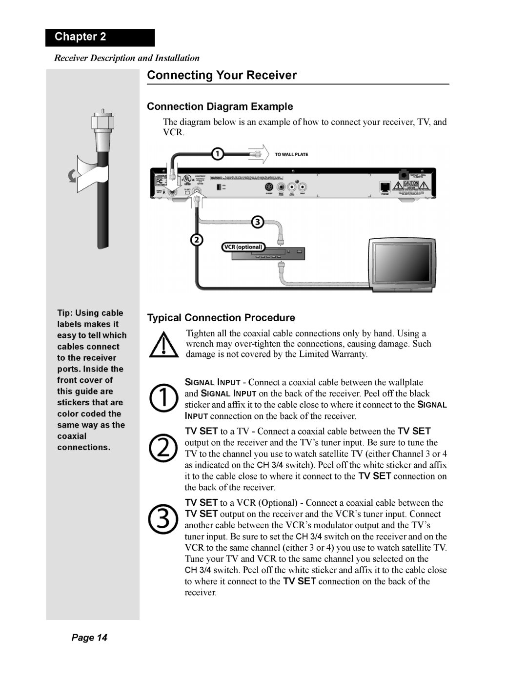
The diagram below is an example of how to connect your receiver, TV, and VCR.
Typical Connection Procedure
Tighten all the coaxial cable connections only by hand. Using a wrench may
SIGNAL INPUT - Connect a coaxial cable between the wallplate and SIGNAL INPUT on the back of the receiver. Peel off the black sticker and affix it to the cable close to where it connect to the SIGNAL INPUT connection on the back of the receiver.
TV SET to a TV - Connect a coaxial cable between the TV SET output on the receiver and the TV’s tuner input. Be sure to tune the TV to the channel you use to watch satellite TV (either Channel 3 or 4 as indicated on the CH 3/4 switch). Peel off the white sticker and affix it to the cable close to where it connect to the TV SET connection on the back of the receiver.
TV SET to a VCR (Optional) - Connect a coaxial cable between the TV SET output on the receiver and the VCR’s tuner input. Connect another cable between the VCR’s modulator output and the TV’s tuner input. Be sure to set the CH 3/4 switch on the receiver and on the VCR to the same channel (either 3 or 4) you use to watch satellite TV. Tune your TV and VCR to the same channel you selected on the CH 3/4 switch. Peel off the white sticker and affix it to the cable close to where it connect to the TV SET connection on the back of the receiver.
Page 14