|
|
|
|
| 18 |
|
Control stage - Cont. |
|
|
| |||
H | R | Function |
| Remark |
| |
|
|
|
| |||
9 | 24a | CCW disable | Two modes - see chapter 7.1.1 ** | |||
10 | 24c | Inhibit input | Two modes - see chapter 7.1.1 * | |||
11 | 22a | Circuit common |
|
| ||
12 | 22c | +5V |
|
| 100mA |
|
13 | 20a |
| + 5%, 50mA external load. | |||
14 | 20c | +15V |
| + 5%, 50mA external load. | ||
15 | 18a | Current | command | Ic |
| |
|
| monitor |
| Scale is = | (A/V) | |
|
|
|
|
| 3.75 |
|
16 | 18c | Back EMF output | See Appendix B. |
| ||
17, | 16a, | Inhibit output | A potential free relay contact. Closed when | |||
18 | 16c |
|
|
| amplifier is enabled. |
|
|
|
|
|
| Contact rating: 0.5A, 200V, 10W | |
19 | 14a | DC | power | voltage | 5A max. |
|
|
| output - common |
|
| ||
20 | 14c | DC | power | voltage | 5A max. |
|
|
| output - positive |
|
| ||
|
|
|
|
|
|
|
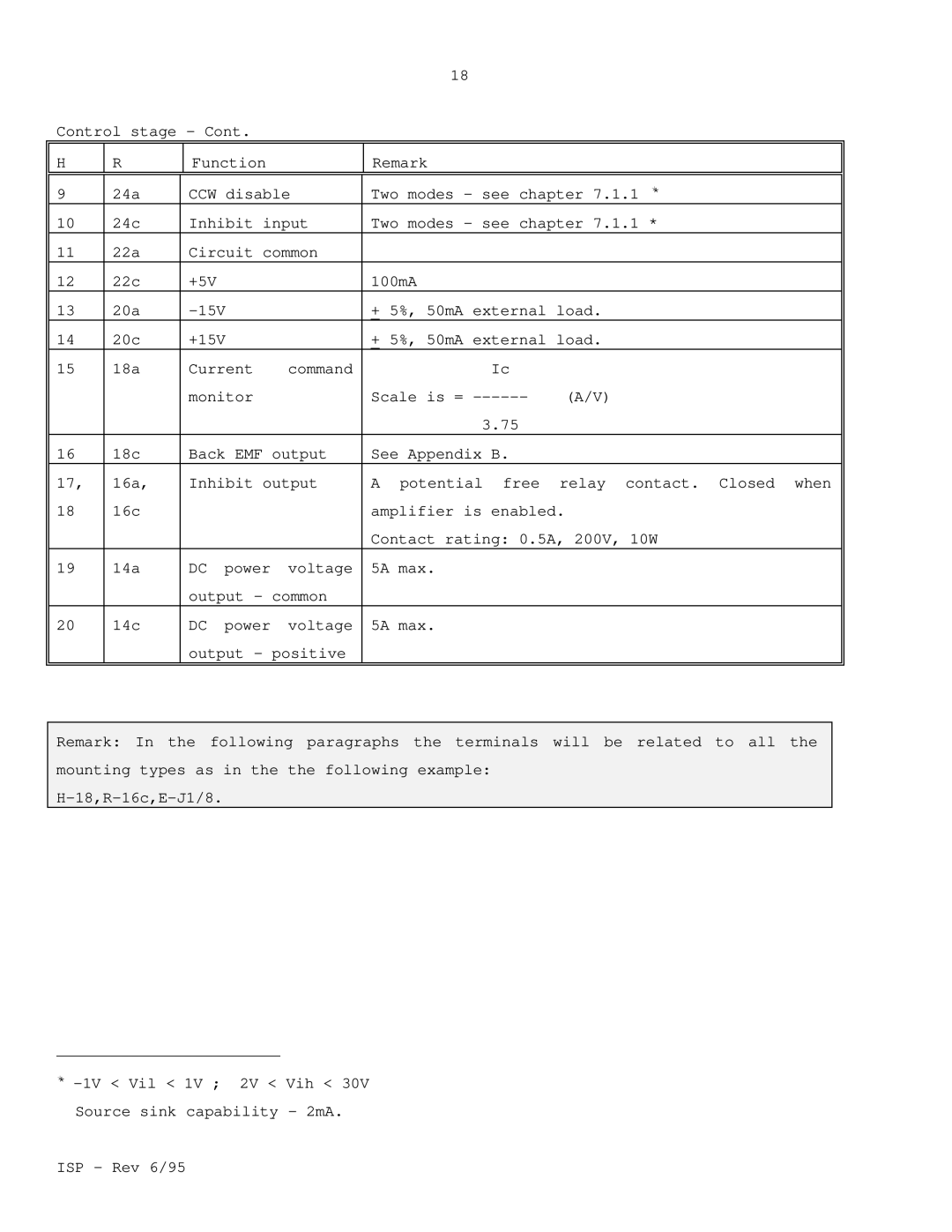
Remark: In the following paragraphs the terminals will be related to all the mounting types as in the the following example:
**
ISP - Rev 6/95
