17
5.Terminal Description
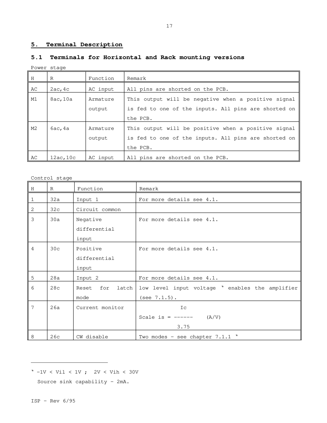
5.1Terminals for Horizontal and Rack mounting versions
Power stage
H | R |
| Function | Remark |
| |||
|
|
|
|
|
|
|
| |
AC | 2ac,4c |
| AC input | All pins are shorted on the PCB. | ||||
M1 | 8ac,10a |
| Armature | This output will be negative when a positive signal | ||||
|
|
|
|
| output | is fed to one of the inputs. All pins are shorted on | ||
|
|
|
|
|
| the PCB. |
| |
M2 | 6ac,4a |
| Armature | This output will be positive when a positive signal | ||||
|
|
|
|
| output | is fed to one of the inputs. All pins are shorted on | ||
|
|
|
|
|
| the PCB. |
| |
AC | 12ac,10c |
| AC input | All pins are shorted on the PCB. | ||||
|
|
|
|
|
|
|
| |
Control stage |
|
|
|
|
| |||
H | R |
| Function |
| Remark |
| ||
|
|
|
|
|
| |||
1 | 32a |
| Input 1 |
| For more details see 4.1. | |||
2 | 32c |
| Circuit common |
|
|
| ||
3 | 30a |
| Negative |
| For more details see 4.1. | |||
|
|
|
| differential |
|
|
| |
|
|
|
| input |
|
|
| |
4 | 30c |
| Positive |
| For more details see 4.1. | |||
|
|
|
| differential |
|
|
| |
|
|
|
| input |
|
|
| |
5 | 28a |
| Input 2 |
| For more details see 4.1. | |||
6 | 28c |
| Reset for latch | low level input | voltage ** enables the amplifier | |||
|
|
|
| mode |
| (see 7.1.5). |
| |
7 | 26a |
| Current monitor |
| Ic |
| ||
|
|
|
|
|
|
| Scale is = | (A/V) |
|
|
|
|
|
|
| 3.75 |
|
8 | 26c |
| CW disable |
| Two modes - see chapter 7.1.1 ** | |||
**
ISP - Rev 6/95