33
7.Start - Up Procedures
All the operations of this chapter do not require power on the unit. The steps of paragraph 7.1 must be performed before proceeding to the appropriate feedback sensor section.
7.1Common procedures for all amplifiers types
7.1.1Inhibit and CW/CCW logic
Select the desired Inhibit and CW/CCW logic you need:
a) Disable by Low
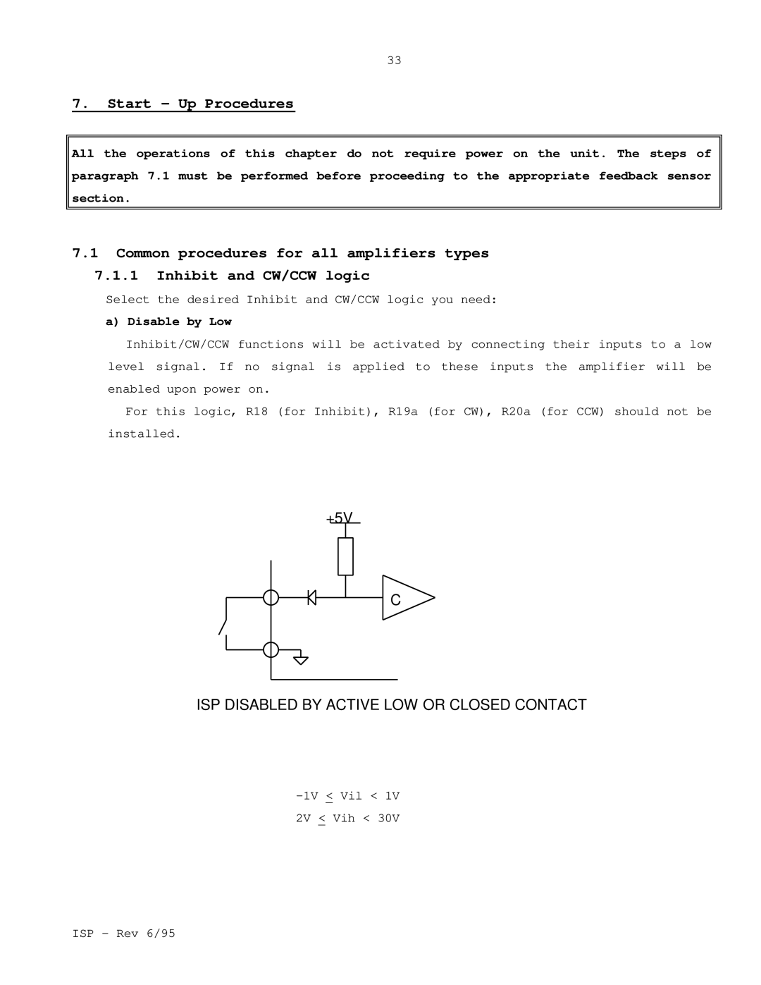
Inhibit/CW/CCW functions will be activated by connecting their inputs to a low level signal. If no signal is applied to these inputs the amplifier will be enabled upon power on.
For this logic, R18 (for Inhibit), R19a (for CW), R20a (for CCW) should not be installed.
+5V
C |
ISP DISABLED BY ACTIVE LOW OR CLOSED CONTACT
2V < Vih < 30V
ISP - Rev 6/95
