9
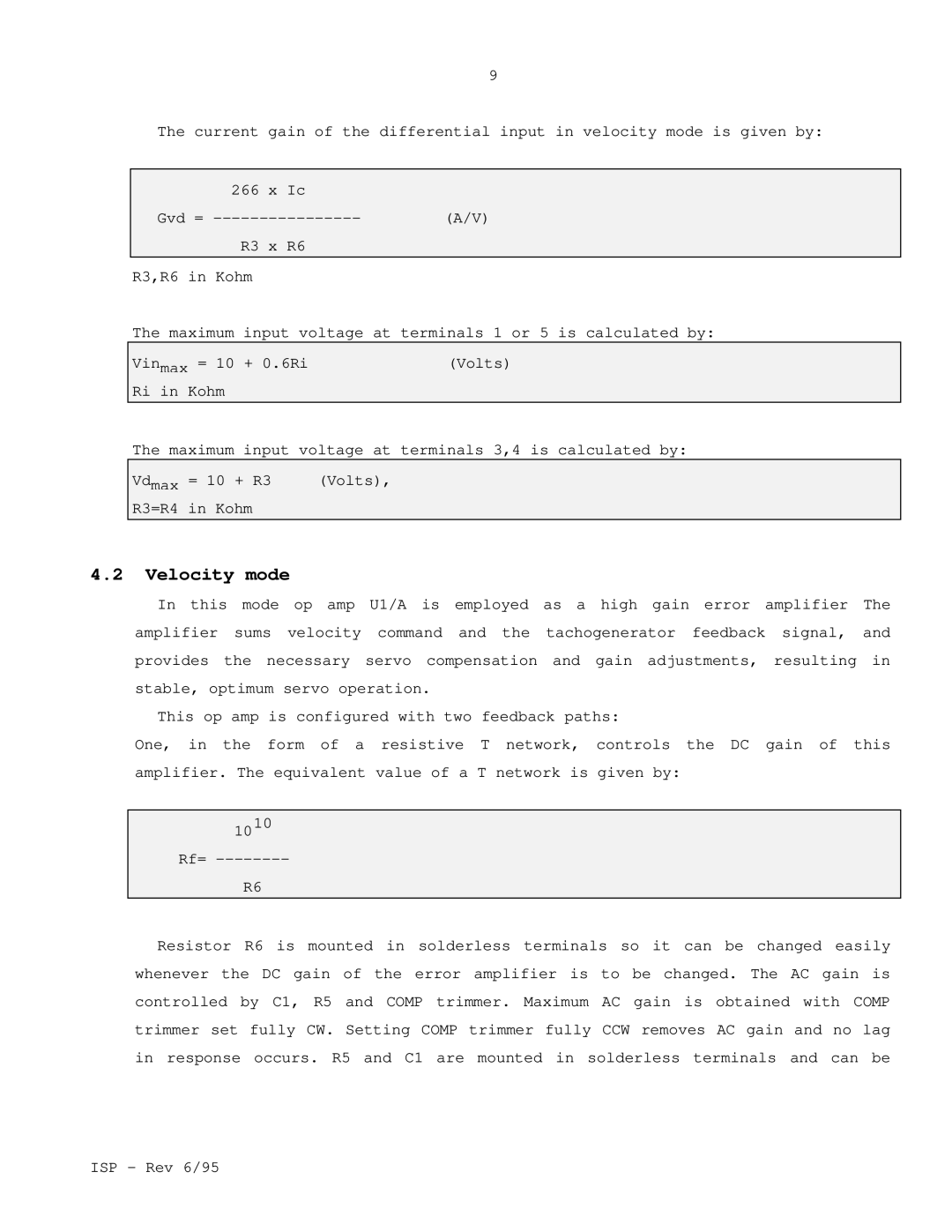
The current | gain of the differential input in velocity mode is given by: |
|
|
266 | x Ic |
Gvd = | (A/V) |
R3 | x R6 |
R3,R6 in Kohm |
|
The maximum input voltage at terminals 1 or 5 is calculated by:
Vinmax = 10 + 0.6Ri(Volts)
Ri in Kohm
The maximum input voltage at terminals 3,4 is calculated by:
Vdmax | = 10 + R3 | (Volts), |
R3=R4 | in Kohm |
|
4.2Velocity mode
In this mode op amp U1/A is employed as a high gain error amplifier The amplifier sums velocity command and the tachogenerator feedback signal, and provides the necessary servo compensation and gain adjustments, resulting in stable, optimum servo operation.
This op amp is configured with two feedback paths:
One, in the form of a resistive T network, controls the DC gain of this amplifier. The equivalent value of a T network is given by:
1010
Rf=
R6
Resistor R6 is mounted in solderless terminals so it can be changed easily whenever the DC gain of the error amplifier is to be changed. The AC gain is controlled by C1, R5 and COMP trimmer. Maximum AC gain is obtained with COMP trimmer set fully CW. Setting COMP trimmer fully CCW removes AC gain and no lag in response occurs. R5 and C1 are mounted in solderless terminals and can be
ISP - Rev 6/95