|
|
| 23 |
|
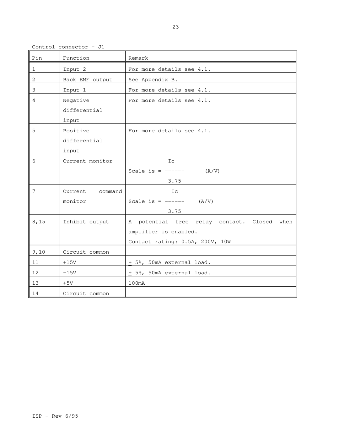
Control connector - J1 |
|
| ||
Pin | Function |
| Remark |
|
|
|
|
| |
1 | Input 2 |
| For more details see 4.1. | |
2 | Back EMF output | See Appendix B. |
| |
3 | Input 1 |
| For more details see 4.1. | |
4 | Negative |
| For more details see 4.1. | |
| differential |
|
| |
| input |
|
|
|
5 | Positive |
| For more details see 4.1. | |
| differential |
|
| |
| input |
|
|
|
6 | Current monitor | Ic |
| |
|
|
| Scale is = | (A/V) |
|
|
| 3.75 |
|
7 | Current | command | Ic |
|
| monitor |
| Scale is = | (A/V) |
|
|
| 3.75 |
|
8,15 | Inhibit output | A potential free relay contact. Closed when | ||
|
|
| amplifier is enabled. |
|
|
|
| Contact rating: 0.5A, 200V, 10W | |
9,10 | Circuit common |
|
| |
11 | +15V |
| + 5%, 50mA external load. | |
12 |
| + 5%, 50mA external load. | ||
13 | +5V |
| 100mA |
|
14 | Circuit common |
|
| |
|
|
|
|
|
ISP - Rev 6/95
