47
Appendix B - Current limits contour adjustment
The amplifier can be configured to have either continuous current limit or peak current limit or both which depend on motor velocity feedback. This function is enabled by calculating and inserting R11, R13.
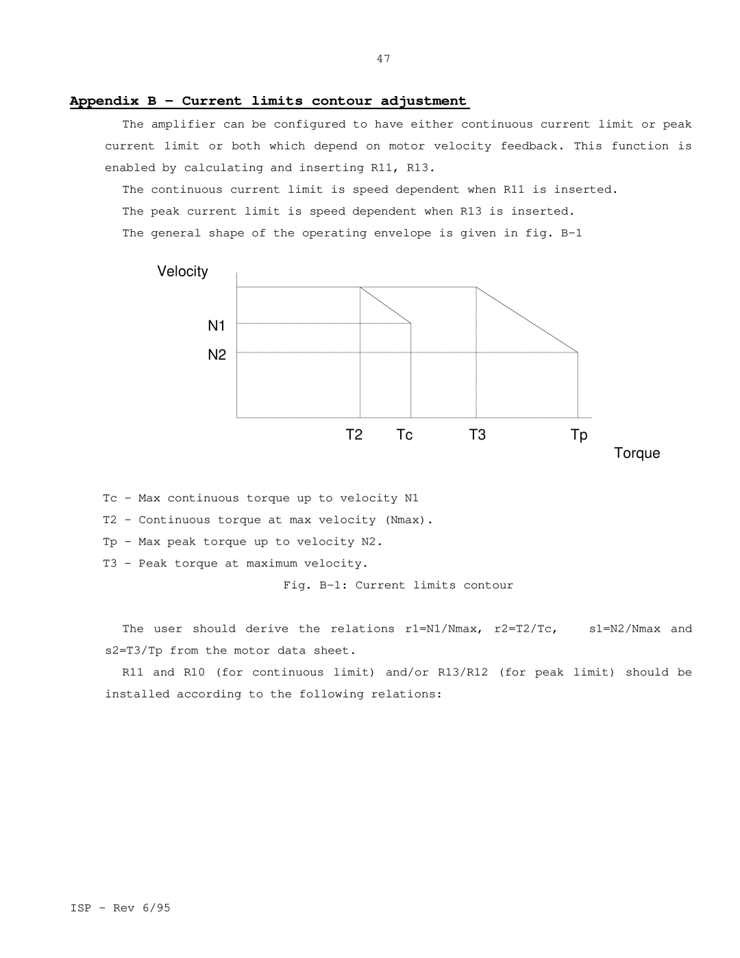
The continuous current limit is speed dependent when R11 is inserted. The peak current limit is speed dependent when R13 is inserted.
The general shape of the operating envelope is given in fig.
Velocity |
|
|
|
N1 |
|
|
|
N2 |
|
|
|
T2 | Tc | T3 | Tp |
Torque
Tc - Max continuous torque up to velocity N1
T2 - Continuous torque at max velocity (Nmax).
Tp - Max peak torque up to velocity N2.
T3 - Peak torque at maximum velocity.
Fig. B-1: Current limits contour
The user should derive the relations r1=N1/Nmax, r2=T2/Tc, | s1=N2/Nmax and |
s2=T3/Tp from the motor data sheet. |
|
