Ocarina/Castanet Installation Guide | Servo Control Operation | |
| ||
|
| |
|
|
|
4.3.5External Resistor
RECLP (Kohm) = 37.4 * Ip(new) - 1
Ip(nom)
Connect an external resistor between terminal J1/14 (ECLP) and terminal J1/8 (ECLRET). The resistor value is given by:
0 < RECLP < 36.4 K (1/8 Watt)
At RECLP greater than 36.4 K, the current limit will be internally clamped to the nominal value.
IP(nom) is the nominal peak current limit of the amplifier.
4.3.6Latch Mode (LM)
By connecting J1/7 to J1/15, the amplifier is latched to disable mode whenever a Short, Commutation or Over Temperature failure occurs. Disabling the amplifier temporarily by removing the power from Enable pin J1/1 resets the latch. Be sure to restore the Enable connection when the reason for the event no longer exists.
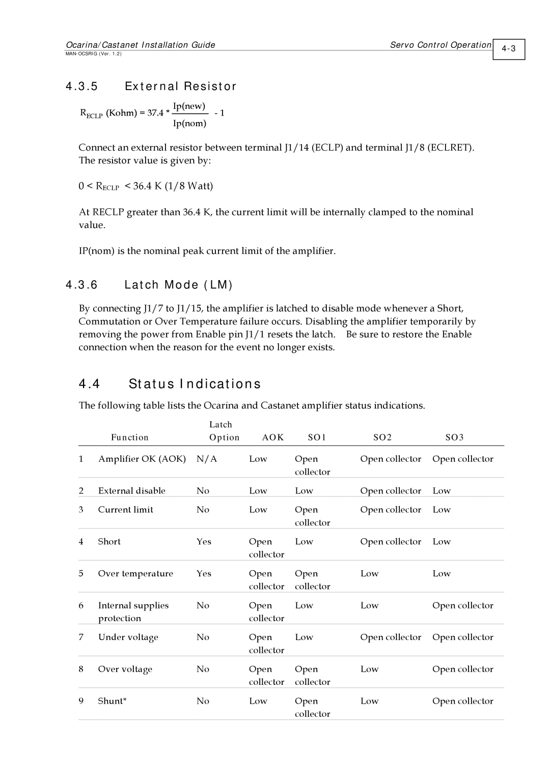
4.4Status Indications
The following table lists the Ocarina and Castanet amplifier status indications.
|
| Latch |
|
|
|
|
| Function | Option | AOK | SO1 | SO2 | SO3 |
|
|
|
|
|
|
|
1 | Amplifier OK (AOK) | N/A | Low | Open | Open collector | Open collector |
|
|
|
| collector |
|
|
2 | External disable | No | Low | Low | Open collector | Low |
3 | Current limit | No | Low | Open | Open collector | Low |
|
|
|
| collector |
|
|
4 | Short | Yes | Open | Low | Open collector | Low |
|
|
| collector |
|
|
|
5 | Over temperature | Yes | Open | Open | Low | Low |
|
|
| collector | collector |
|
|
6 | Internal supplies | No | Open | Low | Low | Open collector |
| protection |
| collector |
|
|
|
7 | Under voltage | No | Open | Low | Open collector | Open collector |
|
|
| collector |
|
|
|
8 | Over voltage | No | Open | Open | Low | Open collector |
|
|
| collector | collector |
|
|
9 | Shunt* | No | Low | Open | Low | Open collector |
|
|
|
| collector |
|
|