Emerson 00825-0100-4530 Rev EC Load limitations, continued, Quick Installation Guide, 435Ω, March

Models: 00825-0100-4530 Rev EC

1 36
Download 36 pages 54.13 Kb
Page 12
Image 12
Load limitations

Quick Installation Guide

March 2013


Step 3 continued...

Load limitations

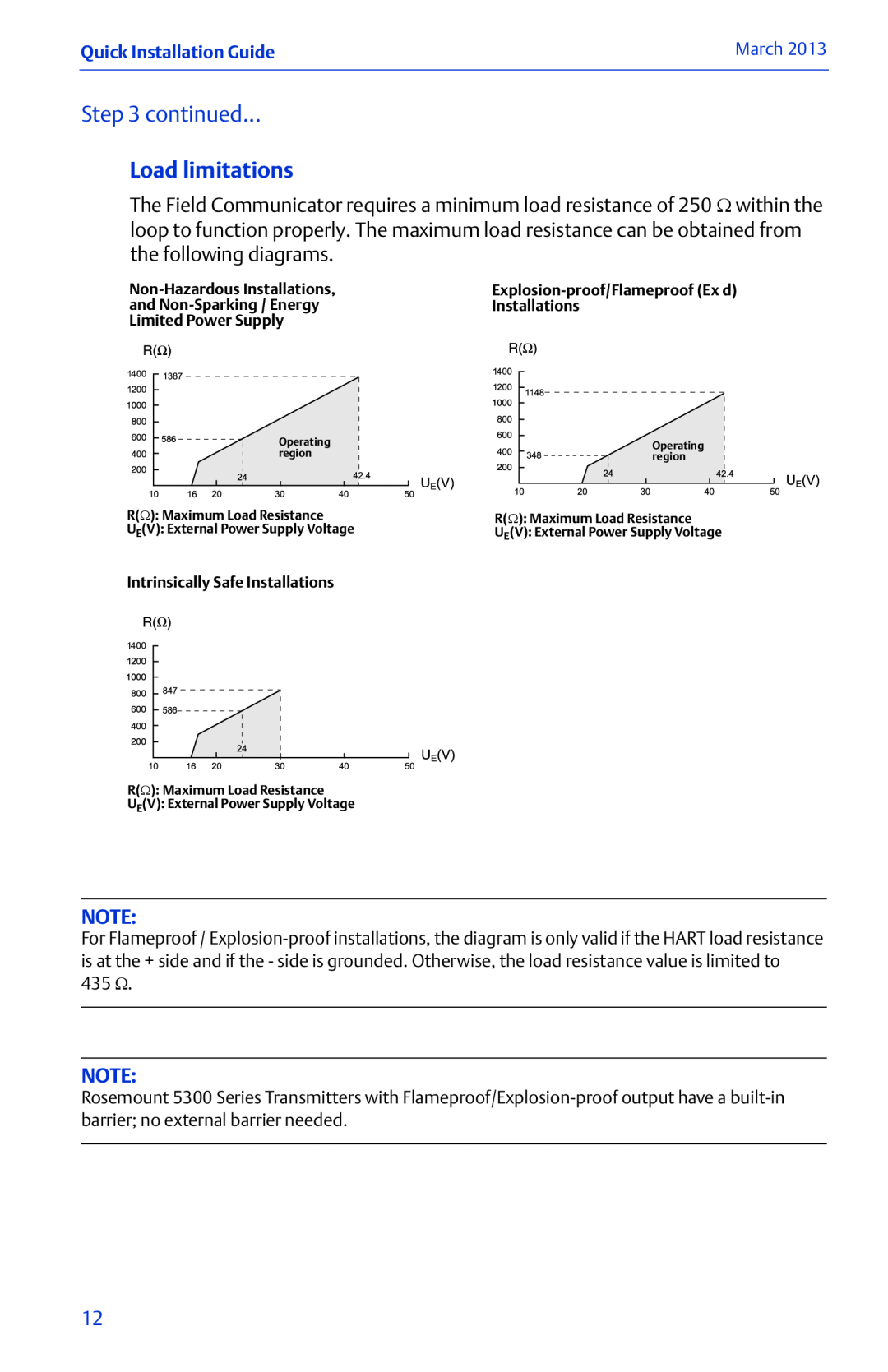
The Field Communicator requires a minimum load resistance of 250 Ω within the loop to function properly. The maximum load resistance can be obtained from the following diagrams.

Non-Hazardous Installations,Explosion-proof/Flameproof (Ex d)
and Non-Sparking / EnergyInstallations
Limited Power Supply


Operating region
Operating
region
R(Ω): Maximum Load Resistance

R(Ω): Maximum Load Resistance

UE(V): External Power Supply VoltageU (V): External Power Supply Voltage


E

Intrinsically Safe Installations

R(Ω): Maximum Load Resistance

UE(V): External Power Supply Voltage

NOTE:

For Flameproof / Explosion-proof installations, the diagram is only valid if the HART load resistance is at the + side and if the - side is grounded. Otherwise, the load resistance value is limited to

435Ω.

NOTE:

Rosemount 5300 Series Transmitters with Flameproof/Explosion-proof output have a built-in barrier; no external barrier needed.

12

Page 12
Image 12
Emerson 00825-0100-4530 Rev EC Load limitations, continued, Quick Installation Guide, 435Ω, March, Installations, region