Emerson 51-DO-04 Installing the air compressor enclosure, Assembling the pipe and pipe clamp

Models: 51-DO-04 51-DO-03 DO-04 DO-03

1 70
Download 70 pages 4.9 Kb
Page 14
Image 14

MODEL DO-03/04

SECTION 2.0


INSTALLATION

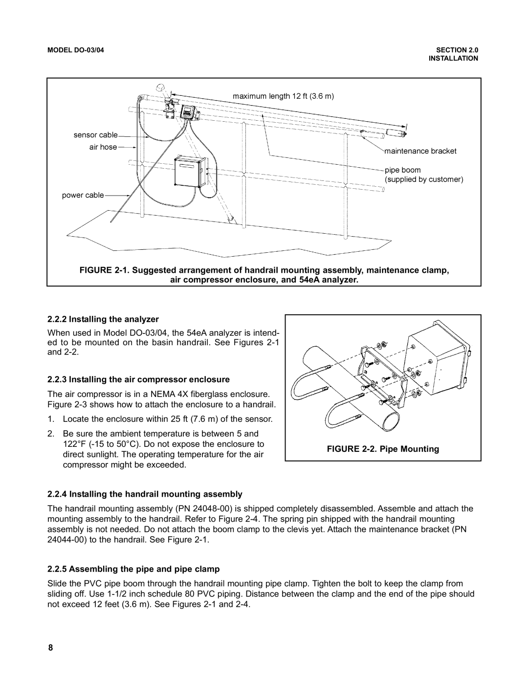
FIGURE 2-1. Suggested arrangement of handrail mounting assembly, maintenance clamp,

air compressor enclosure, and 54eA analyzer.

2.2.2 Installing the analyzer

When used in Model DO-03/04, the 54eA analyzer is intend- ed to be mounted on the basin handrail. See Figures 2-1 and 2-2.

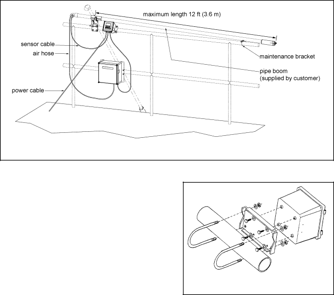
2.2.3 Installing the air compressor enclosure

The air compressor is in a NEMA 4X fiberglass enclosure. Figure 2-3 shows how to attach the enclosure to a handrail.

1.Locate the enclosure within 25 ft (7.6 m) of the sensor.

2.Be sure the ambient temperature is between 5 and 122°F (-15 to 50°C). Do not expose the enclosure to direct sunlight. The operating temperature for the air compressor might be exceeded.

2.2.4 Installing the handrail mounting assembly

FIGURE 2-2. Pipe Mounting

The handrail mounting assembly (PN 24048-00) is shipped completely disassembled. Assemble and attach the mounting assembly to the handrail. Refer to Figure 2-4. The spring pin shipped with the handrail mounting assembly is not needed. Do not attach the boom clamp to the clevis yet. Attach the maintenance bracket (PN 24044-00) to the handrail. See Figure 2-1.

2.2.5 Assembling the pipe and pipe clamp

Slide the PVC pipe boom through the handrail mounting pipe clamp. Tighten the bolt to keep the clamp from sliding off. Use 1-1/2 inch schedule 80 PVC piping. Distance between the clamp and the end of the pipe should not exceed 12 feet (3.6 m). See Figures 2-1 and 2-4.

8

Page 14
Image 14
Emerson 51-DO-04, 51-DO-03 Installing the air compressor enclosure, Installing the handrail mounting assembly