MODEL | SECTION 5.0 |
| SOFTWARE CONFIGURATION |
5.6 CHANGING ALARM PARAMETERS
1.This section describes how to configure the analyzer alarms. Alarms 1, 2, and 3 can be assigned to dissolved oxygen or temperature. In addition, alarm 1, 2, or 3 can be configured as a feed limit timer or as an interval timer (see steps 10 and 11). Alarm 4 is always a fault alarm.
Output setpoints
Simulated tests
Configure
ExitEnter
Outputs Alarms pH
ExitEnter
Alarm 1 control
Alarm 1 setup
Alarm 2 control
ExitEnter
Activation method Control mode
ExitEnter
2.Press any key to enter the main menu. Move the cursor to "Program" and press Enter (F4).
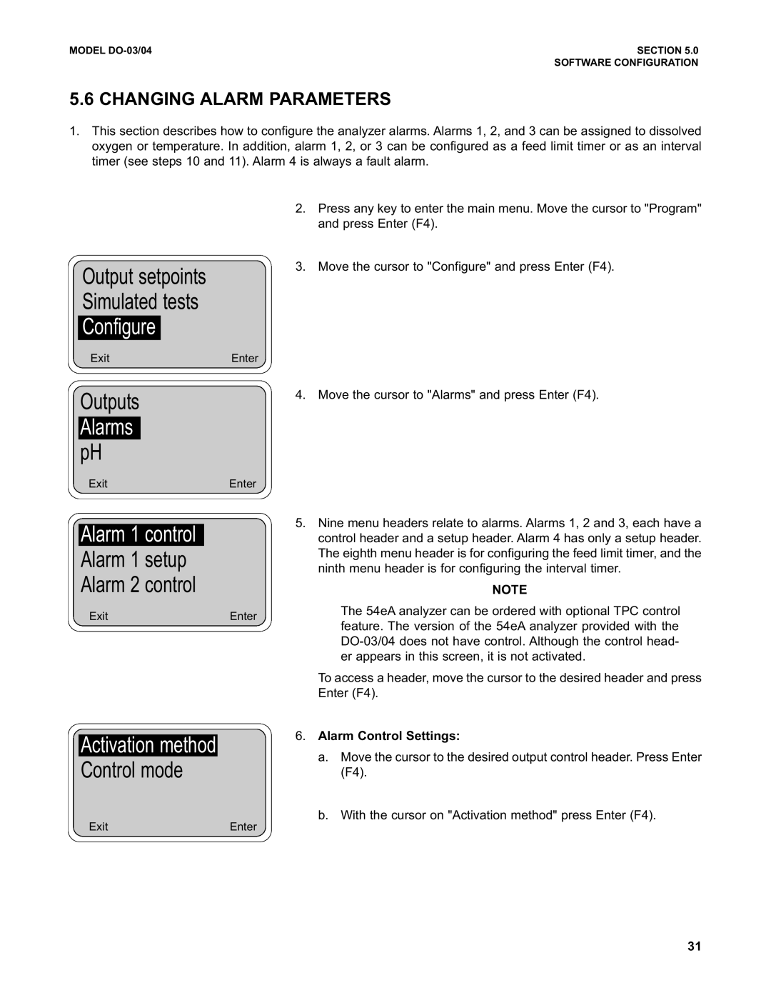
3.Move the cursor to "Configure" and press Enter (F4).
4. Move the cursor to "Alarms" and press Enter (F4).
5.Nine menu headers relate to alarms. Alarms 1, 2 and 3, each have a control header and a setup header. Alarm 4 has only a setup header. The eighth menu header is for configuring the feed limit timer, and the ninth menu header is for configuring the interval timer.
NOTE
The 54eA analyzer can be ordered with optional TPC control feature. The version of the 54eA analyzer provided with the
To access a header, move the cursor to the desired header and press Enter (F4).
6.Alarm Control Settings:
a.Move the cursor to the desired output control header. Press Enter (F4).
b.With the cursor on "Activation method" press Enter (F4).
31