Installation Manual
![]() 5100 Series, Catalog 5150
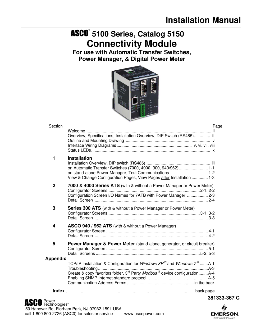
5100 Series, Catalog 5150
Connectivity Module
For use with Automatic Transfer Switches,
Power Manager, & Digital Power Meter
Section | Page |
Welcome | ii |
Overview, Specifications, Installation Overview, DIP Switch (RS485) | .............. iii |
Outline and Mounting Drawing | iv |
Interface Wiring Diagrams | v, vi, vii, viii |
Status LEDs | ix |
1 | Installation |
|
| Installation Overview, DIP switch (RS485) | iii |
| on Automatic Transfer Switches (7000, 4000, 300, 940/962) | |
| on | |
| View & Change Configuration Pages, View Pages after Installation |
27000 & 4000 Series ATS (with & without a Power Manager or Power Meter)
Configurator Screens | |
Configuration Screen I/O Names for 7ATB with Power Manager | |
Detail Screen |
3Series 300 ATS (with & without a Power Manager or Power Meter)
Configurator Screens | |
Detail Screen |
4ASCO 940 / 962 ATS (with & without a Power Manager)
Configurator Screen | |
Detail Screen |
5Power Manager & Power Meter
Configurator Screen | ........................................................................................ |
Detail Screens |
Appendix
TCP/IP Installation & Configuration for Windows XP ® and Windows 7 ® | ||
Troubleshooting | ||
Create & copy favorites folder, 3rd Party Modbus ® device configuration | ||
Enabling SNMP | ||
Communication Address Forms | in the back | |
Index | back page | |
381333-367 C
50 Hanover Rd, Florham Park, NJ |
|
call 1 800 | www.ascopower.com |