Connectivity Module | Overview, Specifications, Installation Overview, DIP Switch iii |
Overview
The Connectivity Module brings together several different serial devices that communicate at different baud rates and with different protocols to a common Ethernet media. It can communicate with up to eight clients, such as Web applications (web pages), Vpi, or
Specifications
Power Requirements: | 24 V dc nominal (8 – 28 V dc) | ||
| 1.5 Watt, UL Class 2 power supply, if needed. | ||
Mounting: |
|
| 35 mm DIN rail |
Dimensions: | 3.5” H, 2.8” W, 2.9” D (8.9 cm, 7.1 cm, 7.4 cm) | ||
Field Communication Cable Requirements: | |||
Ethernet: | Belden 7882A or equiv. UTP CAT 5 with | ||
| RJ45 connectors (untwisted pair or higher) | ||
Serial: | Belden 9842, 9829, 89729, 82729 or Apha | ||
| 6202C, 6222C, 58902. UL Listed, stranded, | ||
twisted pairs, | |||
J1, J2 TTL Port Connectors: | Two | ||
| (DB9 pin male) for ATS/PM connectivity | ||
J3 Ethernet Port Connector :
One
J4 Serial
One
Terminal 1 | – RX+ | Terminal 4 | – TX- |
Terminal 2 | – RX- | Terminal 5 | – Com |
Terminal 3 | – TX+ |
|
|
Ambient Temperature: |
|
Operating | 32 to 140° F (0 to 60° C) |
Storage - |
Configuration Parameters: The parameters that are required to make an Ethernet connection are:
IP Address | 169.254.1.1 |
Subnet Mask | 255.255.0.0 |
Gateway0.0.0.0 |
|
TCP Port No. | 10001 |
The TCP port is used for passing the data to the applications and is configurable for user specific requirement.
Baud Rates | 19200 (default) or 9600 |
Flow Control | No Flow Control (default) |
Interface Mode | TTL/RS485 – 4 wires (default) |
Reply Timeout | 200 milliseconds (default) |
Protocol Support: The following protocols are supported:
Serial Protocol: |
| ASCO I, II, and Modbus |
Transport Protocol: | TCP, UDP | |
Application Protocol: HTTP, Telnet, Modbus/TCP | ||
AES Encryption | enable or disable | |
Installation Overview
1.Determine the kind of network to use to connect the various devices to the Connectivity Module.
2.If a RS485 network will be used, do not install the Connectivity Module until the DIP switches are checked and set on the bottom of the unit. See below.
3.Refer to the outline & mounting drawing (page iv) and wiring diagrams (pages v, vi).
4.Select the appropriate installation (pages
5.Establish and test communications (page
6.View and change configuration pages (page
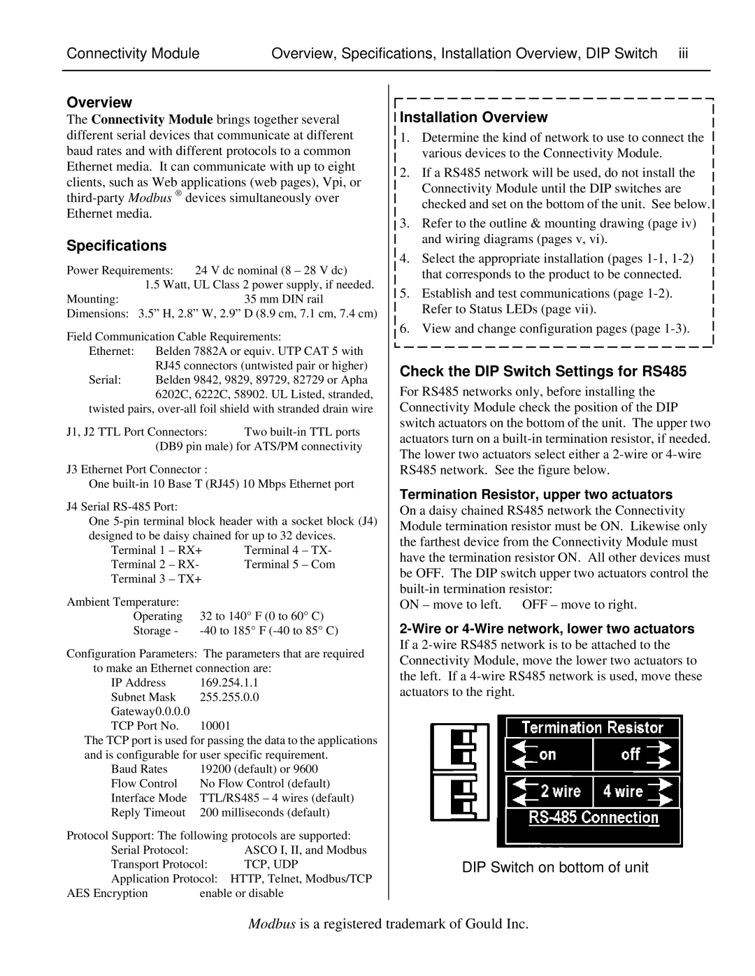
Check the DIP Switch Settings for RS485
For RS485 networks only, before installing the Connectivity Module check the position of the DIP switch actuators on the bottom of the unit. The upper two actuators turn on a
Termination Resistor, upper two actuators
On a daisy chained RS485 network the Connectivity Module termination resistor must be ON. Likewise only the farthest device from the Connectivity Module must have the termination resistor ON. All other devices must be OFF. The DIP switch upper two actuators control the
ON – move to left. OFF – move to right.
2-Wire or 4-Wire network, lower two actuators
If a
DIP Switch on bottom of unit
Modbus is a registered trademark of Gould Inc.