Connectivity Module | Series 300 ATSs |
Detail Screen for Series 300 ATSs
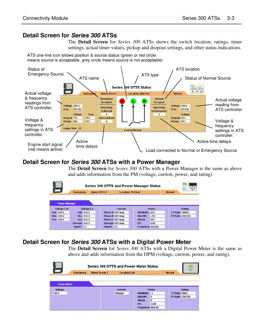
The Detail Screen for Series 300 ATSs shows the switch location, ratings, timer settings, actual timer values, pickup and dropout settings, and other status indications.
ATS
Status of |
|
| ATS location | |
Emergency Source | ATS name | ATS type | Status of Normal Source | |
|
| |||
Actual voltage |
|
|
| |
& frequency |
|
| Actual voltage | |
readings from |
|
| ||
|
| reading from | ||
ATS controller. |
|
| ||
|
| ATS controller. | ||
|
|
| ||
Voltage & |
|
| Voltage & | |
frequency |
|
| frequency | |
settings in ATS |
|
| settings in ATS | |
controller. |
|
| controller. | |
Engine start signal | Active |
| Active time delays | |
time delays |
|
| ||
(red means active) | Load connected to Normal or Emergency Source | |||
| ||||
Detail Screen for Series 300 ATSs with a Power Manager
The Detail Screen for Series 300 ATSs with a Power Manager is the same as above and adds information from the PM (voltage, current, power, and rating).
Detail Screen for Series 300 ATSs with a Digital Power Meter
The Detail Screen for Series 300 ATSs with a Digital Power Meter is the same as above and adds information from the DPM (voltage, current, power, and rating).