Connectivity Module | 7000 & 4000 Series ATSs |
Configurator Screen Input and Output Names for a 7ATB with Power Manager
For 7ATB only (7000 Series Automatic Transfer &
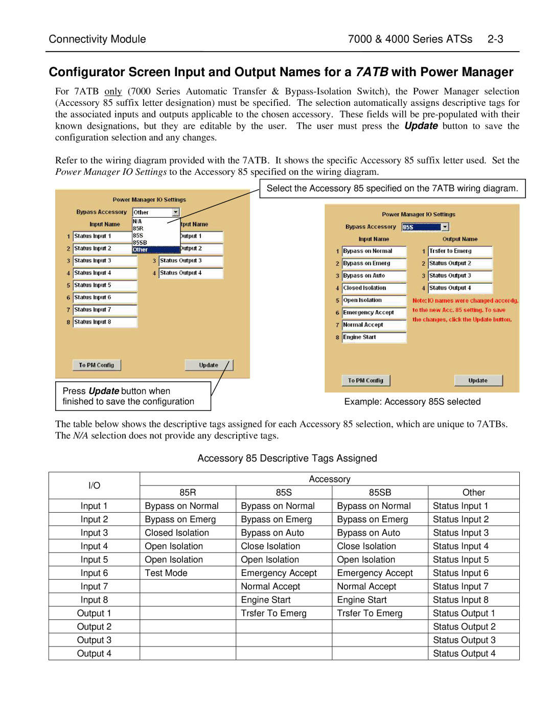
Refer to the wiring diagram provided with the 7ATB. It shows the specific Accessory 85 suffix letter used. Set the Power Manager IO Settings to the Accessory 85 specified on the wiring diagram.
Select the Accessory 85 specified on the 7ATB wiring diagram.
Press Update button when finished to save the configuration
Example: Accessory 85S selected
The table below shows the descriptive tags assigned for each Accessory 85 selection, which are unique to 7ATBs. The N/A selection does not provide any descriptive tags.
Accessory 85 Descriptive Tags Assigned
I/O |
| Accessory | ||
85R | 85S | 85SB | ||
| ||||
Input 1 | Bypass on Normal | Bypass on Normal | Bypass on Normal | |
Input 2 | Bypass on Emerg | Bypass on Emerg | Bypass on Emerg | |
Input 3 | Closed Isolation | Bypass on Auto | Bypass on Auto | |
Input 4 | Open Isolation | Close Isolation | Close Isolation | |
Input 5 | Open Isolation | Open Isolation | Open Isolation | |
Input 6 | Test Mode | Emergency Accept | Emergency Accept | |
Input 7 |
| Normal Accept | Normal Accept | |
Input 8 |
| Engine Start | Engine Start | |
Output 1 |
| Trsfer To Emerg | Trsfer To Emerg | |
Output 2 |
|
|
| |
Output 3 |
|
|
| |
Output 4 |
|
|
| |
Other
Status Input 1
Status Input 2
Status Input 3
Status Input 4
Status Input 5
Status Input 6
Status Input 7
Status Input 8
Status Output 1
Status Output 2
Status Output 3
Status Output 4