| Connectivity Module |
Detail Screen for 7000 & 4000 Series ATSs
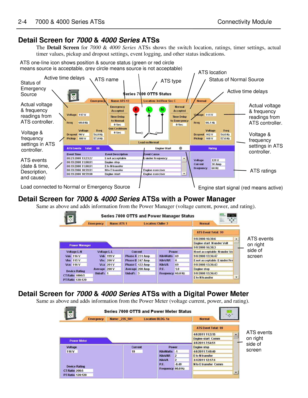
The Detail Screen for 7000 & 4000 Series ATSs shows the switch location, ratings, timer settings, actual timer values, pickup and dropout settings, event logging, and other status indications.
ATS
Active time delays | ATS name | ATS type |
Status of | ||
Emergency |
|
|
Source |
|
|
Actual voltage
&frequency readings from ATS controller.
Voltage & frequency settings in ATS controller.
ATS events (date & time, Description, and cause)
Load connected to Normal or Emergency Source
ATS location
Status of Normal Source
Active time delays
Actual voltage & frequency readings from ATS controller.
Voltage & frequency settings in ATS controller.
ATS ratings
Engine start signal (red means active)
Detail Screen for 7000 & 4000 Series ATSs with a Power Manager
Same as above and adds information from the Power Manager (voltage current, power, and rating).
ATS events on right side of screen
Detail Screen for 7000 & 4000 Series ATSs with a Digital Power Meter
Same as above and adds information from the Power Meter (voltage current, power, and rating).
ATS events on right side of screen