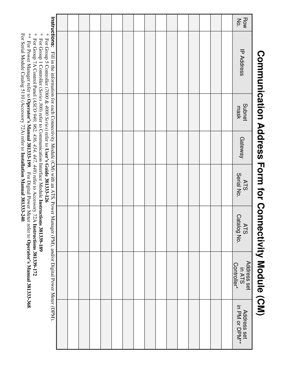
Communication Address Form for Connectivity Module (CM)
Row
No.
IP Address
Subnet
mask
Gateway
ATS
Serial No.
ATS
Catalog No.
Address set
in ATS
Controller*
Address set
in PM or DPM**
Instructions: Fill in the information for each Connectivity Module (CM) with an ATS, Power Manager (PM), and/or Digital Power Meter (DPM).
*For Group 5 Controller (7000 & 4000 Series) refer to User’s Guide
*For Group 1 Controller (Series 300) refer to Communication Interface Module Instructions
*For Group 7A Control Panel (ASCO 940, 962, 436, 434, 447, 448) refer to Accessory 72A Instructions
**For Power Manager refer to Operator’s Manual