Installation and Configuration
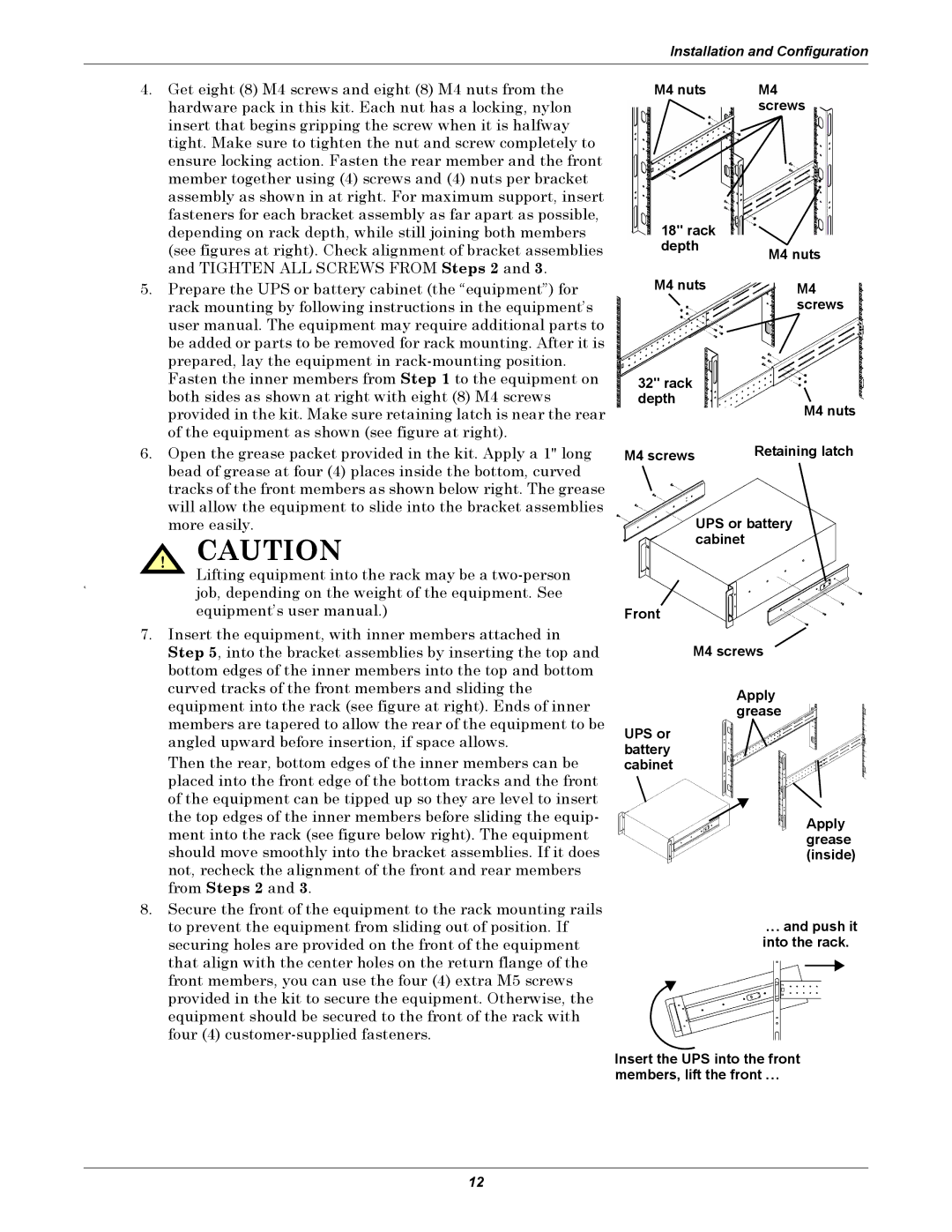
4.Get eight (8) M4 screws and eight (8) M4 nuts from the hardware pack in this kit. Each nut has a locking, nylon insert that begins gripping the screw when it is halfway tight. Make sure to tighten the nut and screw completely to ensure locking action. Fasten the rear member and the front member together using (4) screws and (4) nuts per bracket assembly as shown in at right. For maximum support, insert fasteners for each bracket assembly as far apart as possible, depending on rack depth, while still joining both members (see figures at right). Check alignment of bracket assemblies and TIGHTEN ALL SCREWS FROM Steps 2 and 3.
5.Prepare the UPS or battery cabinet (the “equipment”) for rack mounting by following instructions in the equipment’s user manual. The equipment may require additional parts to be added or parts to be removed for rack mounting. After it is prepared, lay the equipment in
6.Open the grease packet provided in the kit. Apply a 1" long bead of grease at four (4) places inside the bottom, curved tracks of the front members as shown below right. The grease will allow the equipment to slide into the bracket assemblies more easily.
! CAUTION
Lifting equipment into the rack may be a
6.job, depending on the weight of the equipment. See equipment’s user manual.)
7.Insert the equipment, with inner members attached in Step 5, into the bracket assemblies by inserting the top and bottom edges of the inner members into the top and bottom curved tracks of the front members and sliding the equipment into the rack (see figure at right). Ends of inner members are tapered to allow the rear of the equipment to be angled upward before insertion, if space allows.
Then the rear, bottom edges of the inner members can be placed into the front edge of the bottom tracks and the front of the equipment can be tipped up so they are level to insert the top edges of the inner members before sliding the equip- ment into the rack (see figure below right). The equipment should move smoothly into the bracket assemblies. If it does not, recheck the alignment of the front and rear members from Steps 2 and 3.
8.Secure the front of the equipment to the rack mounting rails to prevent the equipment from sliding out of position. If securing holes are provided on the front of the equipment that align with the center holes on the return flange of the front members, you can use the four (4) extra M5 screws provided in the kit to secure the equipment. Otherwise, the equipment should be secured to the front of the rack with four (4)
M4 nuts | M4 |
| screws |
18" rack |
|
depth | M4 nuts |
| |
M4 nuts | M4 |
| screws |
32" rack
depth
M4 nuts
M4 screws | Retaining latch |
UPS or battery cabinet
Front
M4 screws
Apply grease
UPS or battery cabinet
Apply grease (inside)
... and push it into the rack.
Insert the UPS into the front
members, lift the front ...
12