MVME55006E Single-Board Computer
Contact Address
Contents
Contents
RAM55006E Memory Expansion Module
Specifications
Related Documentation
List of Tables
List of Tables
14 VIO Keying Pin Settings
List of Figures
List of Figures
Overview of Contents
About this Manual
Notation Description
Conventions
About this Manual Model Number Description
Bold
About this Manual Notation Description
Summary of Changes
Comments and Suggestions
Date Change Replaces
About this Manual
Introduction
Hardware Preparation and Installation
Overview
Getting Started
Unpacking Guidelines
Overview of Startup Procedures
Hardware Preparation and Installation
Startup Overview
Configuring the Hardware
Configuring the Hardware
Configuring the Board
MVME5500 Jumper Settings
Jumpers Switches Function Settings
Items in brackets are factory default settings
Configuring the BoardHardware Preparation and Installation
Ethernet
2.2 PMC/SBC Mode Selection
Front Panel and Rear P2 Ethernet Settings
J102 J110 Settings
Flash Boot Bank Select Header J8
Flash 0 Programming Enable Switch S3-1
Flash Boot Bank Select Header J8
Safe Start ENV Switch S5-1
Flash 0 Block Write Protect Switch S3-2
S5-1 Settings
Srom Initialization Enable Switch S5-2
PCI Bus 0.0 Speed Switch S4-1
Srom Initialization Enable Switch S5-2
S4-2 Settings
PCI Bus 1.0 Speed Switch S4-2
J27 Settings
VME Scon Select Header J27
S3-3 Settings
Eeprom Write Protect Switch S3-3
Setting the PMC Vio Keying Pin
Eeprom Write Protect Switch S3-3
Installing the RAM5500 Module
Procedure
Installing PMCs
Installing PMCs
Mounting the PMC Module
15 Typical Placement of a PMC Module on a VME Module
Primary PMCspan
16 PMCspan Installation on a VME Module
Primary PMCspan
Secondary PMCspan
Installing the Board
Installing the Board
MVME5500 Connectors
Connector Function
Connection to Peripherals
Completing the Installation
Applying Power
Switches and Indicators
Startup and Operation
Front-Panel LED Status Indicators
Function Label Color Description
Block Diagram
Functional Description
Feature Description
Features
MVME5500 Features Summary
Functional Description
System Controller
Processor
L3 Cache
ProcessorFunctional Description
Interrupt Controller
CPU Bus Interface
Memory Controller Interface
4 I2C Serial Interface and Devices
Direct Memory Access DMA
Direct Memory Access DMA
Timers
Flash Memory
Gigabit Ethernet Interface
System Memory
PCI Local Buses and Devices
2 10/100Mb Ethernet Interface
PCI Idsel Definition
PCI-to-PCI Bridges
PMC Sites
PCI Bus Arbitration
Asynchronous Serial Ports
Real Time Clock and Nvram
VME Interface
Sources of Reset
System Control and Status Registers
PMC Expansion
Debug Support
Functional Description
RAM5500 Feature Summary
RAM55006E Memory Expansion Module
1 RAM5500 Description
Clocks
Memory Expansion Connector Pin Assignments
Srom
RAM55006E Memory Expansion Module
RAM5500 Connector P1 Pin Assignments
Memory Expansion Connector Pin Assignments
Pin Signal
CKD00 CKD01 CKD02 CKD03 CKD04 CKD05
RAM5500 Programming Issues
RAM5500 Programming IssuesRAM55006E Memory Expansion Module
Serial Presence Detect SPD Data
Serial Presence Detect SPD Data
MOTLoad Commands
MOTLoad Firmware
Implementation and Memory Requirements
Utilities
Tests
MOTLoad Firmware
Command List
Command List
MOTLoad Commands
Command Description
MOTLoad FirmwareCommand List
Command ListMOTLoad Firmware
MOTLoad Commands
Using the Command Line Interface
Using the Command Line InterfaceMOTLoad Firmware
Rules
Help
Firmware Settings
Default VME Settings
Firmware SettingsMOTLoad Firmware
PCI Slave Image 4
Default VME Settings
VMEbus Slave Image 0 Translation Offset =
1.1 CR/CSR Settings
Deleting VME Settings
Remote Start
Connector Pin Assignments
Connectors
COM1 Connector J1 Pin Assignments
Asynchronous Serial Port Connector J1
Ethernet Connectors J2
Ethernet Connector J2 Pin Assignments
Ipmc Connector J3
Ipmc Connector J3 Pin Assignments
Ipmc Connector J3
4 PCI/PMC Expansion Connector J4
PCI/PMC Expansion Connector J4 Pin Assignments
PCI/PMC Expansion Connector J4Connector Pin Assignments
AD1 AD0 AD3 AD2 AD5 AD4 AD7 AD6 AD9 AD8
CPU COP Connector J5
CPU COP Connector J5 Pin Assignments
Connector Pin AssignmentsCPU COP Connector J5
PMC 1 Interface Connectors J11, J12, J13, J14
PMC 1 Connector J11 Pin Assignments
PMC 1 Interface Connectors J11, J12, J13, J14
PMC 1 Connector J12 Pin Assignments
PMC 1 Connector J13 Pin Assignments
PMC 1 Connector J14 Pin Assignments
10 Boundary Scan Connector J18 Pin Assignments
Boundary Scan Connector J18
PMC 2 Interface Connectors J21, J22, J23, J24
11 PMC 2 Connector J21 Pin Assignments
12 PMC 2 Connector J22 Pin Assignments
13 PMC 2 Connector J23 Pin Assignments
14 PMC 2 Connector J24 Pin Assignments
Asynchronous Serial Port COM2 Planar Connector J33
15 COM2 Planar Connector J33 Pin Assignments
VMEbus Connectors P1 & P2 PMC Mode
16 VME Connector P2 Pin Assignments PMC Mode
Pin
VMEbus Connectors P1 & P2 SBC Mode
VMEbus Connectors P1 & P2 SBC ModeConnector Pin Assignments
17 VME Connector P2 Pinout with IPMC712
Pin Row Z Row a Row B Row C Row D
18 VME Connector P2 Pinouts with IPMC761
VMEbus Connectors P1 & P2 SBC Mode
Memory Expansion Connector P4
19 Memory Expansion Connector P4 Pin Assignments
Memory Expansion Connector P4Connector Pin Assignments
Connector Pin AssignmentsHeaders
Headers
Pin Signal J34 J97
J100 J101
J98 J99
22 PMC/SBC Mode Selection Headers J28, J32 Pin Assignments
J28 J32 Pin Signal
23 P2 I/O Selection Headers J102 J110 Pin Assignments
SBC/IPMC712 Mode
SBC/IPMC761 Mode
PMC Mode
24 Flash Boot Bank Select Header J8 Pin Assignments
25 VME Scon Select Header J27 Pin Assignments
Connector Pin Assignments
Environmental Specifications
Specifications
Power Requirements
Supply Current Requirements
SpecificationsEnvironmental Specifications
207,058 hours
Thermal Validation
Thermally Significant Components
Table B-1 Thermally Significant Components
Thermal ValidationThermally Significant Components
100
Component Temperature Measurement
Component Temperature Measurement
Preparation
Measuring Case Temperature
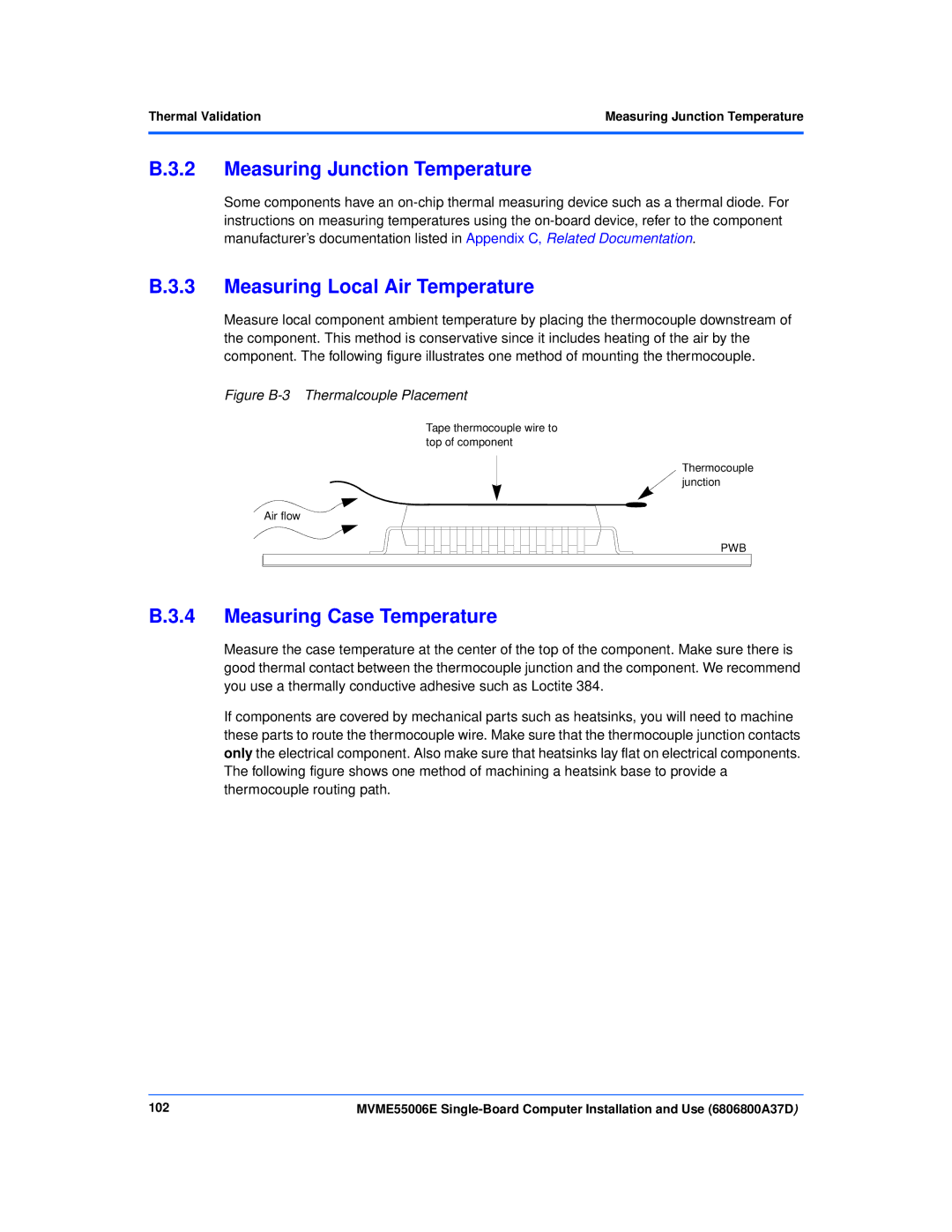
Measuring Junction Temperature
Measuring Local Air Temperature
Thermal Validation
Measuring Case Temperature
Figure B-4 Machining a Heatsink
104
Manufacturers’ Documents
Emerson Network Power Embedded Computing Documents
Related Documentation
Table C-2 Manufacturers’ Documents
Related DocumentationManufacturers’ Documents
106
Related Specifications
Related Specifications
Table C-3 Related Specifications
Document Title and Source Or Search Term
Related Documentation
108
Index
Numerics
110