1
Board Description and Memory Maps
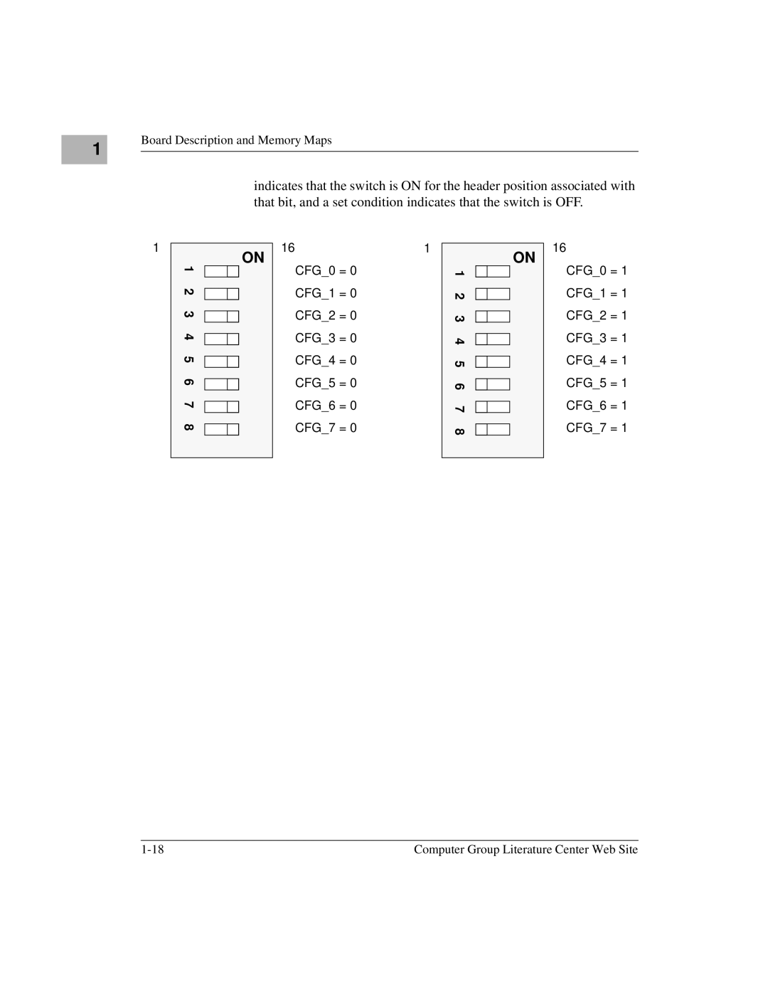
indicates that the switch is ON for the header position associated with that bit, and a set condition indicates that the switch is OFF.
1
1 2 3 4 5 6 7 8
ON
161
CFG_0 = 0
CFG_1 = 0
CFG_2 = 0
CFG_3 = 0
CFG_4 = 0
CFG_5 = 0
CFG_6 = 0
CFG_7 = 0
1 2 3 4 5 6 7 8
ON
16
CFG_0 = 1 CFG_1 = 1 CFG_2 = 1 CFG_3 = 1 CFG_4 = 1 CFG_5 = 1 CFG_6 = 1 CFG_7 = 1
Computer Group Literature Center Web Site |
