Programming Details
2 |
|
|
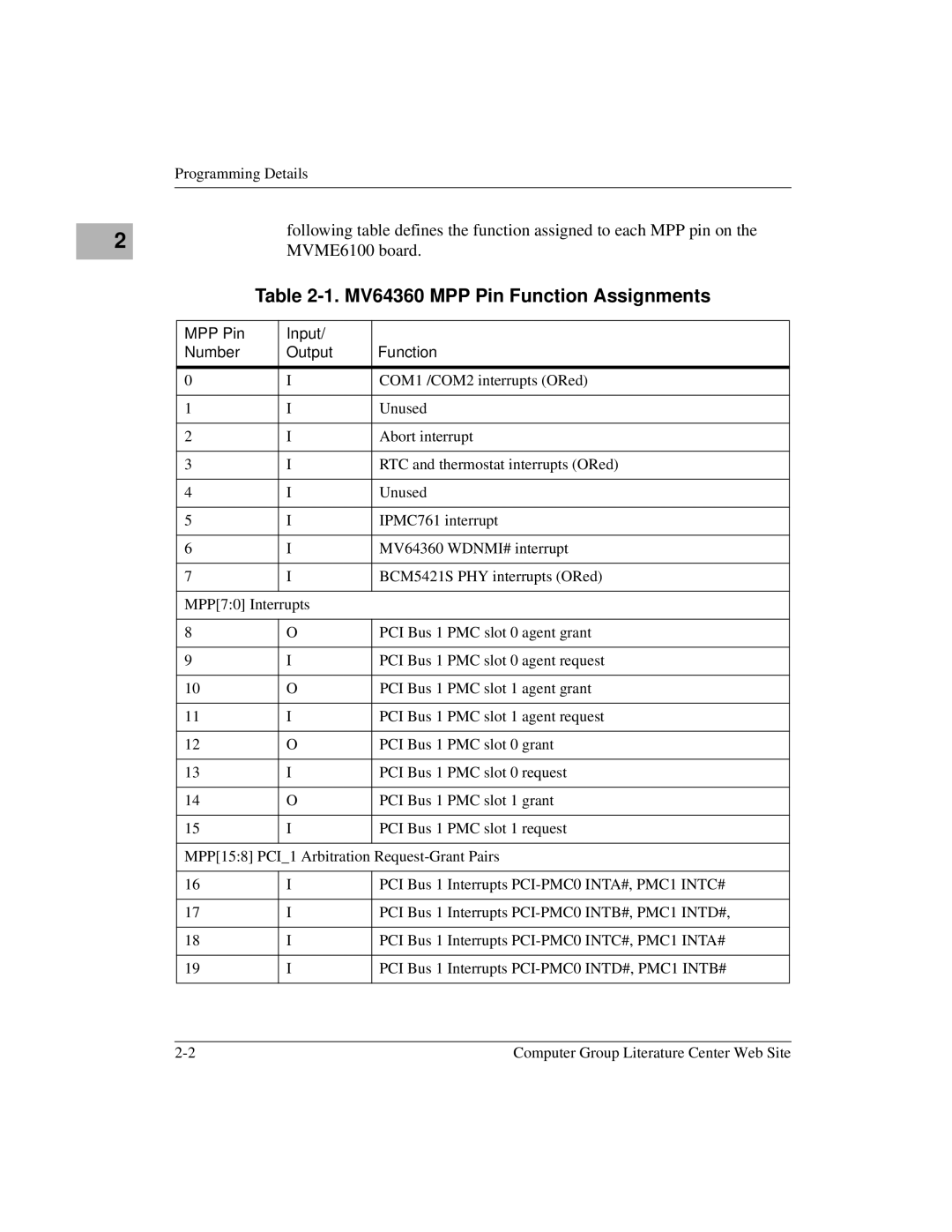
| following table defines the function assigned to each MPP pin on the | |
|
|
| MVME6100 board. | ||
|
|
|
| ||
|
|
| Table | ||
|
|
|
|
|
|
|
| MPP Pin |
| Input/ |
|
|
| Number |
| Output | Function |
|
|
|
|
| |
|
| 0 |
| I | COM1 /COM2 interrupts (ORed) |
|
|
|
|
| |
|
| 1 |
| I | Unused |
|
|
|
|
| |
|
| 2 |
| I | Abort interrupt |
|
|
|
|
| |
|
| 3 |
| I | RTC and thermostat interrupts (ORed) |
|
|
|
|
| |
|
| 4 |
| I | Unused |
|
|
|
|
| |
|
| 5 |
| I | IPMC761 interrupt |
|
|
|
|
| |
|
| 6 |
| I | MV64360 WDNMI# interrupt |
|
|
|
|
| |
|
| 7 |
| I | BCM5421S PHY interrupts (ORed) |
|
|
|
|
| |
|
| MPP[7:0] Interrupts |
| ||
|
|
|
|
| |
|
| 8 |
| O | PCI Bus 1 PMC slot 0 agent grant |
|
|
|
|
| |
|
| 9 |
| I | PCI Bus 1 PMC slot 0 agent request |
|
|
|
|
| |
|
| 10 |
| O | PCI Bus 1 PMC slot 1 agent grant |
|
|
|
|
| |
|
| 11 |
| I | PCI Bus 1 PMC slot 1 agent request |
|
|
|
|
| |
|
| 12 |
| O | PCI Bus 1 PMC slot 0 grant |
|
|
|
|
| |
|
| 13 |
| I | PCI Bus 1 PMC slot 0 request |
|
|
|
|
| |
|
| 14 |
| O | PCI Bus 1 PMC slot 1 grant |
|
|
|
|
| |
|
| 15 |
| I | PCI Bus 1 PMC slot 1 request |
|
|
|
|
| |
|
| MPP[15:8] PCI_1 Arbitration | |||
|
|
|
|
| |
|
| 16 |
| I | PCI Bus 1 Interrupts |
|
|
|
|
| |
|
| 17 |
| I | PCI Bus 1 Interrupts |
|
|
|
|
| |
|
| 18 |
| I | PCI Bus 1 Interrupts |
|
|
|
|
| |
|
| 19 |
| I | PCI Bus 1 Interrupts |
|
|
|
|
|
|
Computer Group Literature Center Web Site |
