Programming Details
2
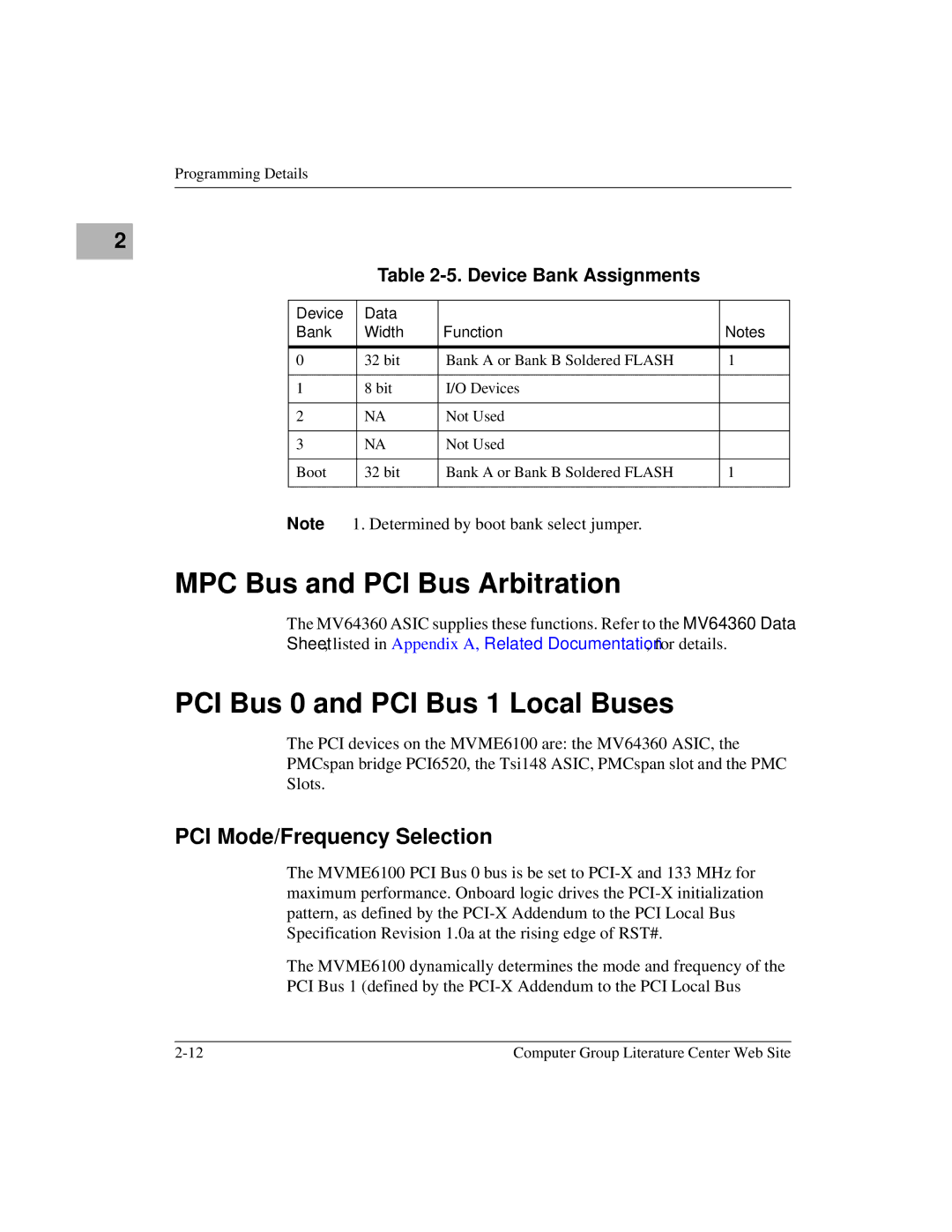
Table 2-5. Device Bank Assignments
Device | Data |
|
|
Bank | Width | Function | Notes |
|
|
|
|
0 | 32 bit | Bank A or Bank B Soldered FLASH | 1 |
|
|
|
|
1 | 8 bit | I/O Devices |
|
|
|
|
|
2 | NA | Not Used |
|
|
|
|
|
3 | NA | Not Used |
|
|
|
|
|
Boot | 32 bit | Bank A or Bank B Soldered FLASH | 1 |
|
|
|
|
Note 1. Determined by boot bank select jumper.
MPC Bus and PCI Bus Arbitration
The MV64360 ASIC supplies these functions. Refer to the MV64360 Data
Sheet, listed in Appendix A, Related Documentation, for details.
PCI Bus 0 and PCI Bus 1 Local Buses
The PCI devices on the MVME6100 are: the MV64360 ASIC, the
PMCspan bridge PCI6520, the Tsi148 ASIC, PMCspan slot and the PMC
Slots.
PCI Mode/Frequency Selection
The MVME6100 PCI Bus 0 bus is be set to
The MVME6100 dynamically determines the mode and frequency of the
PCI Bus 1 (defined by the
Computer Group Literature Center Web Site |
