Precision Cooling
Liebert Xtreme Density
System Design Manual
For Business-Critical Continuity
Page
TABLE OF CONTENTS
1.0 SYSTEM DESCRIPTION
XDH AND LIEBERT XDCF
FIGURES
5.0 SPECIFICATIONS
4.0 LIEBERT XD COOLING MODULES-LIEBERT XDO, LIEBERT XDV, LIEBERT
Figure 24 Hydraulic diagram . . . . . . . . . . . . . . . . . . . . . . . . . . . . . . . . . . . . . . . . . . . . . . . . . . . . . . . . . . . . . . 24 Figure 25 Bypass flow controller details, dimensions . . . . . . . . . . . . . . . . . . . . . . . . . . . . . . . . . . . . . . . . . . . 25 Figure 26 Bypass flow controller arrangement . . . . . . . . . . . . . . . . . . . . . . . . . . . . . . . . . . . . . . . . . . . . . . . . 25 Figure 27 Bypass flow controller piping . . . . . . . . . . . . . . . . . . . . . . . . . . . . . . . . . . . . . . . . . . . . . . . . . . . . . . 25 Figure 28 Dimensional data-Liebert XDO hard-piped units . . . . . . . . . . . . . . . . . . . . . . . . . . . . . . . . . . . . 31 Figure 29 Dimensional data-Liebert XDO with pre-charged option . . . . . . . . . . . . . . . . . . . . . . . . . . . . . . 31 Figure 30 Liebert XDO internal mounting location. . . . . . . . . . . . . . . . . . . . . . . . . . . . . . . . . . . . . . . . . . . . . 32 Figure 31 Liebert XDO top and front electrical access points . . . . . . . . . . . . . . . . . . . . . . . . . . . . . . . . . . . . . 33 Figure 32 Liebert XDV dimensions . . . . . . . . . . . . . . . . . . . . . . . . . . . . . . . . . . . . . . . . . . . . . . . . . . . . . . . . . 34 Figure 33 Liebert XDV dimensions with one-shot connection . . . . . . . . . . . . . . . . . . . . . . . . . . . . . . . . . . . . 35 Figure 34 Liebert XDV electrical connections for CE approved units . . . . . . . . . . . . . . . . . . . . . . . . . . . . . . 36 Figure 35 Liebert XDV electrical connections for CSA-approved units . . . . . . . . . . . . . . . . . . . . . . . . . . . . . 37 Figure 36 Suspending single Liebert XDV from Unistruts . . . . . . . . . . . . . . . . . . . . . . . . . . . . . . . . . . . . . . . 38 Figure 37 Suspending single Liebert XDV from the roof structure . . . . . . . . . . . . . . . . . . . . . . . . . . . . . . . . 38 Figure 38 Alternative mounting methods-mounting multiple Liebert XDV units . . . . . . . . . . . . . . . . . . . 39 Figure 39 Liebert XDCF hydraulic diagram . . . . . . . . . . . . . . . . . . . . . . . . . . . . . . . . . . . . . . . . . . . . . . . . . . 40 Figure 40 Overall dimensions . . . . . . . . . . . . . . . . . . . . . . . . . . . . . . . . . . . . . . . . . . . . . . . . . . . . . . . . . . . . . . 41 Figure 41 Liebert XDCF unit mounting locations . . . . . . . . . . . . . . . . . . . . . . . . . . . . . . . . . . . . . . . . . . . . . . 42 Figure 42 Liebert XDCF supply and return piping access points . . . . . . . . . . . . . . . . . . . . . . . . . . . . . . . . . . 43 Figure 43 Liebert XDH dimensions . . . . . . . . . . . . . . . . . . . . . . . . . . . . . . . . . . . . . . . . . . . . . . . . . . . . . . . . . 44 Figure 44 Supply and return piping connections
TABLES
Figure 1 Pressure enthalpy diagram - refrigerant
Pressure
Enthalpy
1.0 SYSTEM DESCRIPTION
Figure 3 Indirect system configuration-hydraulic system diagram
1.2 Direct and Indirect System Configurations
Figure 2 Direct system configuration-hydraulic system diagram
1.1 European Union Fluorinated Greenhouse Gas Requirements
1.3 Liebert XDO-Overhead Cooling Module
1.4 Liebert XDV-Vertical, Above-Cabinet Cooling Module
1.5 Liebert XDH-Horizontal Cooling Module
1.6 Liebert XDCF
Figure 8 Liebert XDCF units on BladeFrame EX cabinets
1.7 Liebert XDA-Air Flow Enhancer
Figure 10 Liebert XDP pumping unit
1.8 Liebert XDP-Pumping Unit
1.8.1 Liebert XDP Minimum Load
Figure 11 Liebert XD Chiller unit
1.9 Liebert XDC-Refrigerant Chiller
1.9.1 Liebert XDC Minimum Load
1.10.1 Liebert XD Field Piping Flexible Piping Kit
Liebert XD field-installed port kits header connection size
1.10 Liebert XD Piping
Prefabricated Headers
2.1 Determining Cooling Equipment Needs
2.0 STARTING A NEW EQUIPMENT COOLING PROJECT
2.2 Implementing a Hot-Aisle/Cold Aisle Design
Figure 13 Hot aisle-cold aisle arrangement with under-floor source
3.2 Calculate the Heat Load to be Handled by Liebert XD System
3.0 DESIGNING A LIEBERT XD SOLUTION
3.1 Determine Cooling Requirements and Select Liebert XD System
3.3 Selecting Liebert XD Cooling Modules
3.4 Airflow Requirements for Liebert XD Solutions
3.5 Configuring a Liebert XD System
3.5.1 Number of Modules Supported by a Liebert XDP or Liebert XDC
3.6.1 Determining Spacing of Liebert XDOs in an Aisle
3.6 Liebert XDO Placement
Figure 14 Liebert XDO placement over cold aisle
Figure 15 Liebert XDO spacing-horizontal and vertical
3.7 Liebert XDV Unit Placement
Figure 16 Positioning Liebert XDV on top of cabinet
3.8 Liebert XDCF Placement
Figure 17 Liebert XDCF unit mounting locations
Figure 18 Liebert XDH placement
3.9 Liebert XDH Placement
3.10 Liebert XDP/Liebert XDC Placement
Cold Aisle
Interlaced piping arrangement
for enhanced protection
arrangement
Interlaced piping arrangement for enhanced protection
Interlaced piping
for enhanced
Example
3.12 Liebert XD Refrigerant
3.13 Liebert XD Piping System Design
9ft 2.7m max Liebert XDP/ Liebert XDC
Supply, return pipe sizes for refrigerant loop
20ft 6.7m max
Liebert XD Cooling Modules
3.15 Bypass Flow Controllers
Figure 24 Hydraulic diagram
3.14 Liebert XD Piping Slope
Liebert XDC
Figure 26 Bypass flow controller arrangement
Figure 25 Bypass flow controller details, dimensions
Liebert XDP or Liebert XDC
Figure 27 Bypass flow controller piping
System refrigerant charge for the supply and return mains
3.16 Determining Refrigerant Volume
3.16.1 Liebert XDP/Liebert XDC Pumped R-134a Circuit Volume
Supply Line Diameter 1/2
Metal Flex Pipe Connector Length
Refrigerant Charge, lb. kg
Return Line Diameter 5/8
Table 11 Calculating refrigerant charge-example
3.17 Liebert XDC DX R-407c Circuit Volume-Air Cooled Units
3.16.2 Calculating Refrigerant Charge-Example
Table 12 Worksheet to calculate refrigerant charge
3.19 Electrical
3.20 Display Panel and Remote Temperature/Humidity Sensor Locations
3.18 Chilled Water Piping
Table 14 Outdoor condenser charge-R-407c
4.1 Liebert XDO Standard Features
4.1.1 Optional Features Liebert XDO
Left Side
Figure 28 Dimensional data-Liebert XDO hard-piped units
Figure 29 Dimensional data-Liebert XDO with pre-charged option
of XDO 24-1/8
Figure 30 Liebert XDO internal mounting location
TOP OF XDO Mounting Hole Knockouts for Low-Voltage Wiring
4.2 Liebert XDV Standard Features
Mounting Hole Knockouts for High-Voltage Wiring FRONT OF XDO
Figure 31 Liebert XDO top and front electrical access points
4.2.1 Optional Features-Liebert XDV
Figure 32 Liebert XDV dimensions
Detail “A”
Figure 33 Liebert XDV dimensions with one-shot connection
Detail Area “A”
Supply Connection 1/2
60Hz MODELS ONLY FIELD WIRING CONNECTIONS AT TERMINAL STRIP
Knockout for Optional Wiring Primary and Secondary Power Cords
POWER SOURCE
TO BE N.E.C. CLASS USE SWITCH CONTACTS WITH 75 V.A MINIMUM
Rear of XDV Right Side of XDV Condensate Detection Dry Contacts - Low
Voltage Connections Knockout for Optional Wiring IEC Primary and
Secondary Power Inlet
Rear of XDV
Figure 36 Suspending single Liebert XDV from Unistruts
Figure 37 Suspending single Liebert XDV from the roof structure
Attach hanger brackets
Liebert XDC
4.3 Liebert XDCF Standard Features
Figure 39 Liebert XDCF hydraulic diagram
or Liebert XDP
4.4 Liebert XDCF Mechanical Considerations
Figure 40 Overall dimensions
NETWORK POWER
Liebert TM XD
Figure 41 Liebert XDCF unit mounting locations
4.5 Liebert XDCF Installation Considerations
4.6 Liebert XDCF Piping Connection Methods and Points
Figure 42 Liebert XDCF supply and return piping access points
4.7 Liebert XDH Standard Features
4.7.1 Optional Features-Liebert XDH
4.6.1 Header System
Detail “A”
Figure 43 Liebert XDH dimensions
Top of Liebert XDH
Rear
2-1/8 O.D
Return Main
seen from end
Or 2-5/8 O.D
4.8 Liebert XD Flex Pipe Kit
Table 17 Liebert XD Flex Pipe assemblies, supply and return
Supply
4.9 Liebert XD Piping Dimensions and Features
4.9.1 Piping Installation Method prefabricated headers
Return
Supply
Return
Page 3, Rev
Table 20 Five-port prefabricated piping legend
ODS ODR 120 Ref. 3048mm
Supply
Return
7-7/16 Ref. Typ
Figure 50 Liebert XDP dimensions
4.10 Liebert XDP Standard Features
Unit Dimensional Data
Table 22 Liebert XDP dimensions
Figure 51 Liebert XDP piping access points and external features
Table 23 Unit piping outlet connection sizes, inches, OD Cu
Disconnect
Switch
Status Lamps
User Interface
Transformer Power Block Fuse Blocks Transformer
Customer Power
Disconnect Switch
Connection
Figure 56 Liebert XDC dimensional data
4.11 Liebert XDC Standard Features
4.11.1 Liebert XDC Optional Features
Table 24 Liebert XD Chiller dimensions, weight
Figure 57 Liebert XDC piping locations
Table 25 Liebert XD Chiller piping connection sizes
Table 26 Liebert XDC Water/Glycol Piping Connection Sizes
6-1/2
Figure 59 Piping locations-floor stand and valve assembly
10-1/2
Switch
Knockout for Input Power Enclosure Cover Not Shown for Clarity
Switch
Figure 60 Front view of Liebert XDC and electrical enclosures
Transformer Fuse Block
Figure 64 Liebert XDC high voltage connections-secondary disconnect switch, 60Hz models
User Interface Wall Box Wiring Temperature/Humidity Sensor Wiring
Figure 68 Liebert XDC Extra Low Voltage field connections points
5.0 SPECIFICATIONS
Table 27 Liebert XDC160 specifications
XDC160 Water Floor Stand - 60Hz
Table 28 Floor stand specifications-water-cooled Liebert XDC
Models - 60 Hz
Models - 60 Hz
Performance Data
Models - 60 Hz
XDC160 Glycol Floor Stand - 60Hz - 40% EG
Heat Rejection Equipment
Table 31 Liebert XDP160 specifications
Specifications
Table 32 
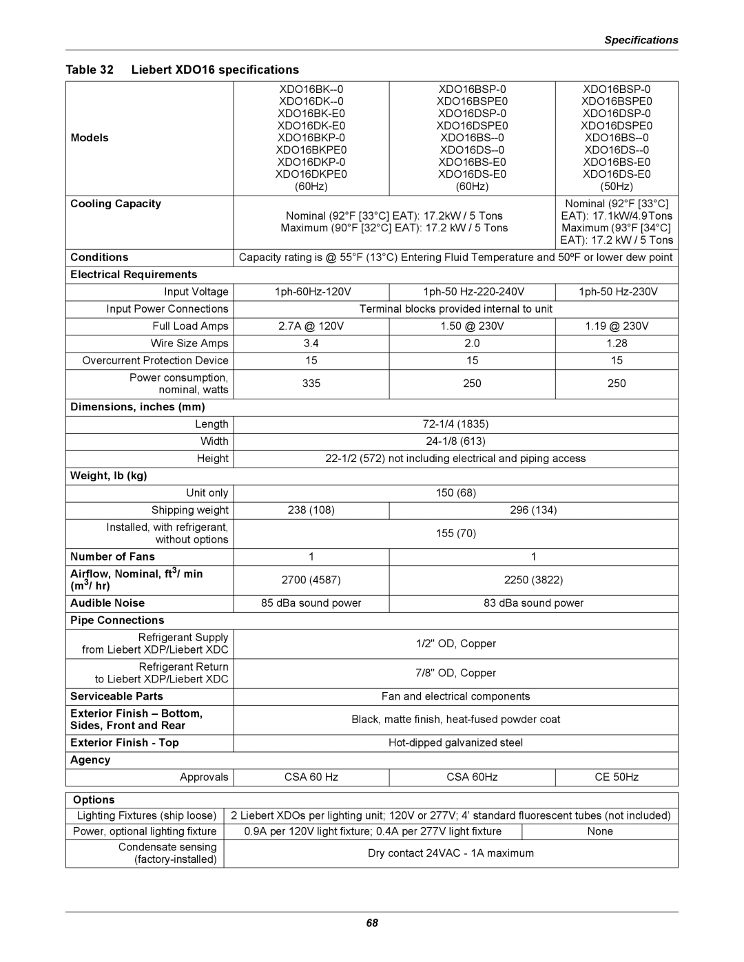
Liebert XDO16 specifications
Specifications
Table 33 Liebert XDO20 specifications
Specifications
Includes piping connections
Table 34 Liebert XDO20 dimensions-domestic and export
Table 35 Liebert XDO16 dimensions-domestic and export
Table 36 Liebert XDV8 specifications
Table 37 Liebert XDV10 specifications
Table 40 Liebert XDCF specifications
Table 38 Liebert XDV8 dimensions-domestic and export
Table 39 Liebert XDV10 dimensions-domestic and export
Specifications
Number of Fans
Table 41 Liebert XDH specifications
Models
Specifications
Specifications
Page
Ne t
Ensuring The High Availability
0f Mission-Critical Data And Applications
ti n