Connecting the Cables
Connecting the Cables
Note: Refer to Appendix C for cabling and
Perform the following steps to connect the cables and power on the access point:
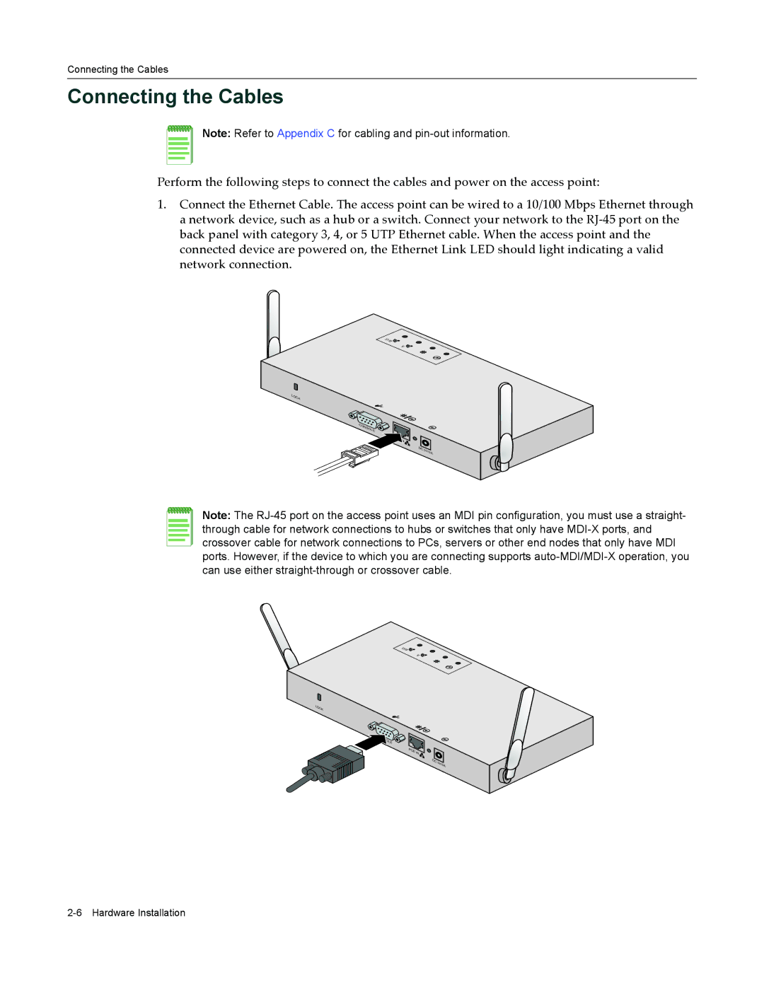
1.Connect the Ethernet Cable. The access point can be wired to a 10/100 Mbps Ethernet through a network device, such as a hub or a switch. Connect your network to the RJ‐45 port on the back panel with category 3, 4, or 5 UTP Ethernet cable. When the access point and the connected device are powered on, the Ethernet Link LED should light indicating a valid network connection.
B/G![]()
A ![]()
![]()
LOCK
C |
ON |
SO |
LE |
DC | 5V/3A |
|
Note: The
B/G![]()
A![]()
LOCK
IN ![]()
DC |
|
5V | |
| /3A |
