Console Port Pin Assignments
Table C-1 Wiring Map for Serial Cable (continued)
Signal (serial port) | Pin | Signal (management console port) |
| | |
RTS (request to send) | 8 | CTS (clear to send) |
| | |
Unused | 9 | Unused |
Note: The left hand column pin assignments are for the female DB-9 connector on the access point. Pin 2 (TXD or “transmit data”) must emerge on the management console’s end of the connection as RXD (“receive data”). Pin 7 (CTS or “clear to send”) must emerge on the management console’s end of the connection as RTS (“request to send”).
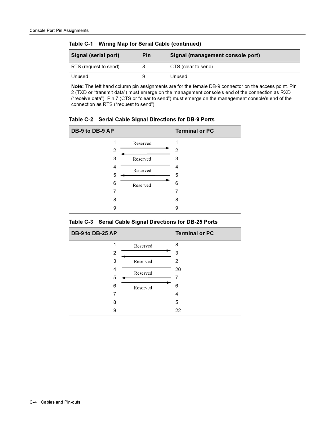
Table C-2 Serial Cable Signal Directions for DB-9 Ports
| DB-9 to DB-9 AP | | | | Terminal or PC |
| | | | | |
| 1 | Reserved | 1 |
| 2 | | 2 |
| |
| 3 | Reserved | 3 |
| 4 | | | 4 |
| Reserved | |
| 5 | 5 |
| |
| 6 | | | |
| Reserved | | 6 |
| 7 | 7 |
| |
| 8 | | 8 |
| 9 | | 9 |
| | | | | |
Table C-3 Serial Cable Signal Directions for DB-25 Ports
| DB-9 to DB-25 AP | | | | Terminal or PC |
| | | | | |
| 1 | Reserved | 8 |
| 2 | | 3 |
| |
| 3 | Reserved | 2 |
| 4 | | | 20 |
| Reserved | |
| 5 | 7 |
| |
| 6 | | | |
| Reserved | | 6 |
| 7 | 4 |
| |
| 8 | | 5 |
| 9 | | 22 |
| | | | | |